Aspire Wireless Firmware Update Instructions
Use the following instructions to update the firmware for the Aspire Wireless DSIU PCBs (P/N 0891090, 0891091, 0891092). The files used for updating the PCBs can be downloaded from the NEC Technical Support web site (ws1.necii.com). This web site requires registration with the NEC Sales Support. Contact them by phone
Updating the DSIU’s Firmware
1. Check Program
2. Download the firmware update files and SIO application from the NEC Technical Support web site.
3. Unzip the SIO application (WinZip application required - this can be downloaded from www.winzip.com).
4. Copy the FLASH.KTB and FLASH2.KTB files into the same directory as the SIO application.
5. Move the RUN/BLOCK switch to the BLOCK position.
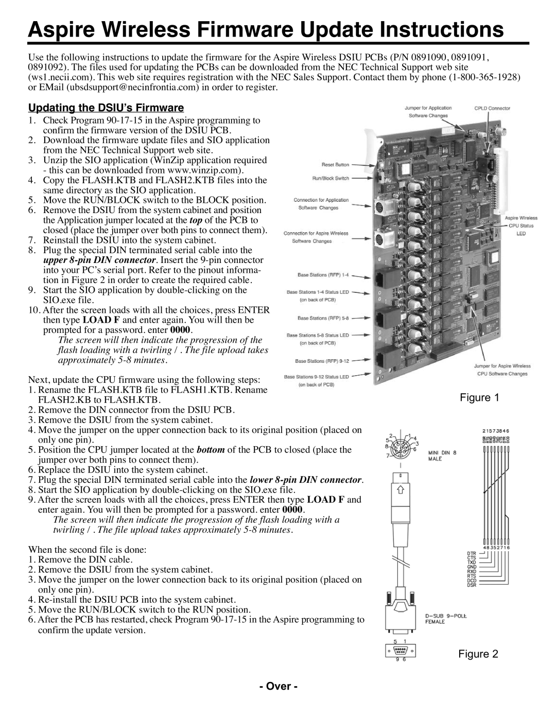
6. Remove the DSIU from the system cabinet and position the Application jumper located at the top of the PCB to closed (place the jumper over both pins to connect them).
7. Reinstall the DSIU into the system cabinet.
8. Plug the special DIN terminated serial cable into the upper
9. Start the SIO application by
10. After the screen loads with all the choices, press ENTER then type LOAD F and enter again. You will then be prompted for a password. enter 0000.
The screen will then indicate the progression of the flash loading with a twirling / . The file upload takes approximately
Next, update the CPU firmware using the following steps: |
|
1. Rename the FLASH.KTB file to FLASH1.KTB. Rename | Figure 1 |
FLASH2.KB to FLASH.KTB. |
2.Remove the DIN connector from the DSIU PCB.
3.Remove the DSIU from the system cabinet.
4.Move the jumper on the upper connection back to its original position (placed on only one pin).
5.Position the CPU jumper located at the bottom of the PCB to closed (place the jumper over both pins to connect them).
6.Replace the DSIU into the system cabinet.
7.Plug the special DIN terminated serial cable into the lower
8.Start the SIO application by
9.After the screen loads with all the choices, press ENTER then type LOAD F and enter again. You will then be prompted for a password. enter 0000.
The screen will then indicate the progression of the flash loading with a twirling / . The file upload takes approximately
When the second file is done:
1.Remove the DIN cable.
2.Remove the DSIU from the system cabinet.
3.Move the jumper on the lower connection back to its original position (placed on only one pin).
4.
5.Move the RUN/BLOCK switch to the RUN position.
6.After the PCB has restarted, check Program
Figure 2