Manuals
/
ASRock
/
Computer Equipment
/
Personal Computer
ASRock
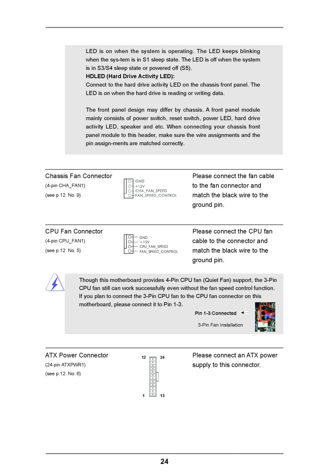
960GM-VGS3 FX Chassis Fan Connector, to the fan connector and, match the black wire to the
Models:
960GM-VGS3 FX
1
24
53
53
Download
53 pages
18.06 Kb
21
22
23
24
25
26
27
28
Specification
Install
Password
PCI Latency Timer
match the black wire to the
CPU Configuration
Jumpers Setup
Command Rate
Connector
Bios Setup Utility
Page 24
Image 24
Page 23
Page 25
Page 24
Image 24
Page 23
Page 25
Contents
960GM-VGS3 FX 960GM-VS3 FX
User Manual
Copyright Notice
Disclaimer
CALIFORNIA, USA ONLY
Contents
Installation
Introduction
3. BIOS SETUP UTILITY
4. Software Support
1.1 Package Contents
1. Introduction
ASRock Reminds You
1.2 Specifications
Platform
Chipset
Memory
Connector
BIOS Feature
Support CD
Hardware
Page
1.3 Unique Features
ASRock Instant Boot
ASRock OC Tuner
ASRock Intelligent Energy Saver
ASRock OC DNA
ASRock APP Charger
ASRock XFast USB
ASRock XFast LAN
ASRock XFast RAM
ASRock X-Boost
1.4 Motherboard Layout 960GM-VGS3 FX / 960GM-VS3 FX
ATXPWR1
SB710
SOCKET AM3b
1.5 I/O Panel 960GM-VGS3 FX
LAN Port LED Indications
1.6 I/O Panel 960GM-VS3 FX
2. Installation
Pre-installation Precautions
2.1 CPU Installation
2.2 Installation of CPU Fan and Heatsink
2.3 Installation of Memory Modules DIMM
Installing a DIMM
Installing an expansion card
2.4 Expansion Slots PCI and PCI Express Slots
2.5 Multi Monitor Feature
For Windows XP / XP 64-bit OS
For Windows 8 / 8 64-bit / 7 / 7 64-bit / VistaTM / VistaTM 64-bit OS
2.6 Jumpers Setup
Description
2.7 Onboard Headers and Connectors
PWRBTN Power Switch
RESET Reset Switch
PLED System Power LED
This header accommodates
Chassis Fan Connector
to the fan connector and
match the black wire to the
CPU Fan Connector
ATX 12V Power Connector
2.8 Serial ATA2 SATA2 Hard Disks Installation
What is Hot Plug Function?
What is Hot Swap Function?
2.9 Hot Plug and Hot Swap Functions for Serial ATA2 SATA2 HDDs
2.10 SATA2 HDD Hot Plug Feature and Operation Guide
Points of attention, before you process the Hot Plug
How to Hot Plug a SATA2 HDD
How to Hot Unplug a SATA2 HDD
2.11 Driver Installation Guide
2.12.1 Installing Windows XP / XP 64-bit With RAID Functions
STEP 1 Set up BIOS
STEP 2 Make a SATA / SATA2 Driver Diskette
STEP 3 Use “RAID Installation Guide” to set RAID configuration
\ RAID Installation Guide
STEP 4 Install Windows XP / XP 64-bit OS on your system
STEP 2 Use “RAID Installation Guide” to set RAID configuration
2.13.1 Installing Windows XP / XP 64-bit Without RAID Functions
Using SATA / SATA2 HDDs with NCQ and Hot Plug functions AHCI mode
STEP 2 Install Windows XP / XP 64-bit OS on your system
Using SATA / SATA2 HDDs without NCQ and Hot Plug functions IDE mode
2.14 Untied Overclocking Technology
3. BIOS SETUP UTILITY
3.1.1 BIOS Menu Bar
Boot
3.1 Introduction
To load optimal default values for all the settings
To save changes and exit the BIOS SETUP UTILITY
3.1.2 Navigation Keys
3.2 Main Screen
960GM-VS3 FX
CPU Configuration Overclock Mode
Boot Failure Guard
Boot Failure Guard Count
3.3 OC Tweaker Screen
Processor Maximum Frequency
North Bridge Maximum Frequency
Processor Maximum Voltage
Multiplier/Voltage Change
Memory Configuration Memory Clock
Power Down Enable
DRAM Frequency
Memory Timing
Command Rate
Chipset Settings Onboard GPU Clock Override
Would you like to save current setting user defaults?
TRFC
3.4 Advanced Screen
Instant Flash
3.4.1 CPU Configuration
Cool ‘n’ Quiet
Secure Virtual Machine
Enhance Halt State C1E
3.4.2 Chipset Configuration
Onboard HD Audio
Front Panel
Onboard Lan
3.4.3 ACPI Configuration
Restore on AC/Power Loss
Ring-In Power On
PCI Devices Power On
ACPI HPET table
3.4.4 Storage Configuration
Onboard SATA Controller
SATA Operation Mode
SATA IDE Combined Mode
3.4.5 PCIPnP Configuration
PCI Latency Timer
PCI IDE BusMaster
3.4.6 Super IO Configuration
Serial Port Address
Infrared Port
Infrared Port Address
3.4.7 USB Configuration
USB Keyboard/Remote Power On
USB Mouse Power On
USB Controller
CPU Fan Setting
Chassis Fan 1 Setting
Case Open Feature
3.5 Hardware Health Event Monitoring Screen
3.6 Boot Screen
3.6.1 Boot Settings Configuration
Boot From Onboard LAN
Bootup Num-Lock
3.7 Security Screen
Security Settings
Change Supervisor Password
Load BIOS Defaults
Load Performance Setup Default
Load Power Saving Setup Default
3.8 Exit Screen
4.1 Install Operating System
4. Software Support
4.2 Support CD Information
4.2.1 Running The Support CD
Top
Page
Image
Contents