2.1 CPU Installation
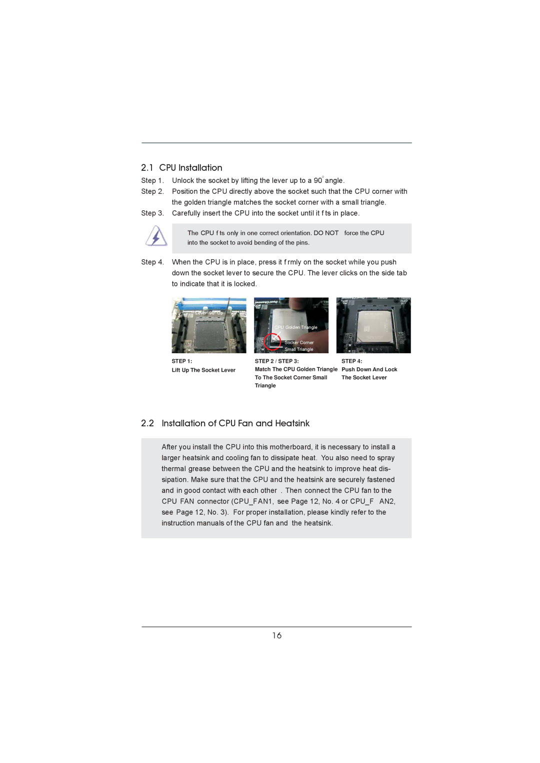
Step 1. | Unlock the socket by lifting the lever up to a 90o angle. | ||
Step 2. | Position the CPU directly above the socket such that the CPU corner with | ||
| the golden triangle matches the socket corner with a small triangle. | ||
Step 3. | Carefully insert the CPU into the socket until it f ts in place. | ||
|
|
| |
| The CPU f ts only in one correct orientation. DO NOT | force the CPU | |
| into the socket to avoid bending of the pins. |
| |
|
| ||
Step 4. | When the CPU is in place, press it f rmly on the socket while you push | ||
| down the socket lever to secure the CPU. The lever clicks on the side tab | ||
| to indicate that it is locked. |
| |
| Lever 90° Up |
|
|
|
| CPU Golden Triangle |
|
|
| Socker Corner |
|
|
| Small Triangle |
|
| STEP 1: | STEP 2 / STEP 3: | STEP 4: |
| Lift Up The Socket Lever | Match The CPU Golden Triangle | Push Down And Lock |
|
| To The Socket Corner Small | The Socket Lever |
|
| Triangle |
|
2.2 Installation of CPU Fan and Heatsink
After you install the CPU into this motherboard, it is necessary to install a larger heatsink and cooling fan to dissipate heat. You also need to spray thermal grease between the CPU and the heatsink to improve heat dis- sipation. Make sure that the CPU and the heatsink are securely fastened and in good contact with each other . Then connect the CPU fan to the CPU FAN connector (CPU_FAN1, see Page 12, No. 4 or CPU_F AN2, see Page 12, No. 3). For proper installation, please kindly refer to the instruction manuals of the CPU fan and the heatsink.
16
