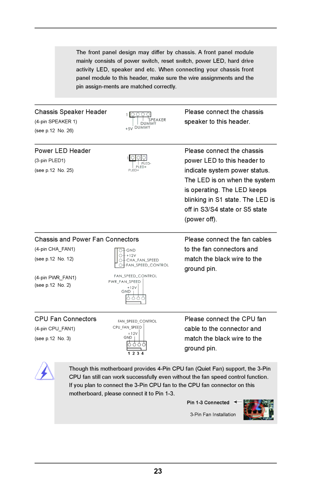
The front panel design may differ by chassis. A front panel module mainly consists of power switch, reset switch, power LED, hard drive activity LED, speaker and etc. When connecting your chassis front panel module to this header, make sure the wire assignments and the pin
Chassis Speaker Header | Please connect the chassis |
speaker to this header. | |
(see p.12 No. 26) |
|
|
|
Power LED Header | Please connect the chassis |
power LED to this header to | |
(see p.12 No. 25) | indicate system power status. |
| The LED is on when the system |
| is operating. The LED keeps |
| blinking in S1 state. The LED is |
| off in S3/S4 state or S5 state |
| (power off). |
|
|
Chassis and Power Fan Connectors | Please connect the fan cables |
to the fan connectors and | |
(see p.12 No. 12) | match the black wire to the |
| ground pin. |
| |
(see p.12 No. 2) |
|
CPU Fan Connectors | FAN_SPEED_CONTROL | |||
CPU_FAN_SPEED | ||||
(see p.12 No. 3) | +12V |
| ||
GND |
|
|
| |
| 1 | 2 | 3 | 4 |
Please connect the CPU fan cable to the connector and match the black wire to the ground pin.
Though this motherboard provides
Pin
23