Copyright Notice
Disclaimer
English
Motherboard Layout
Activity/Link LED
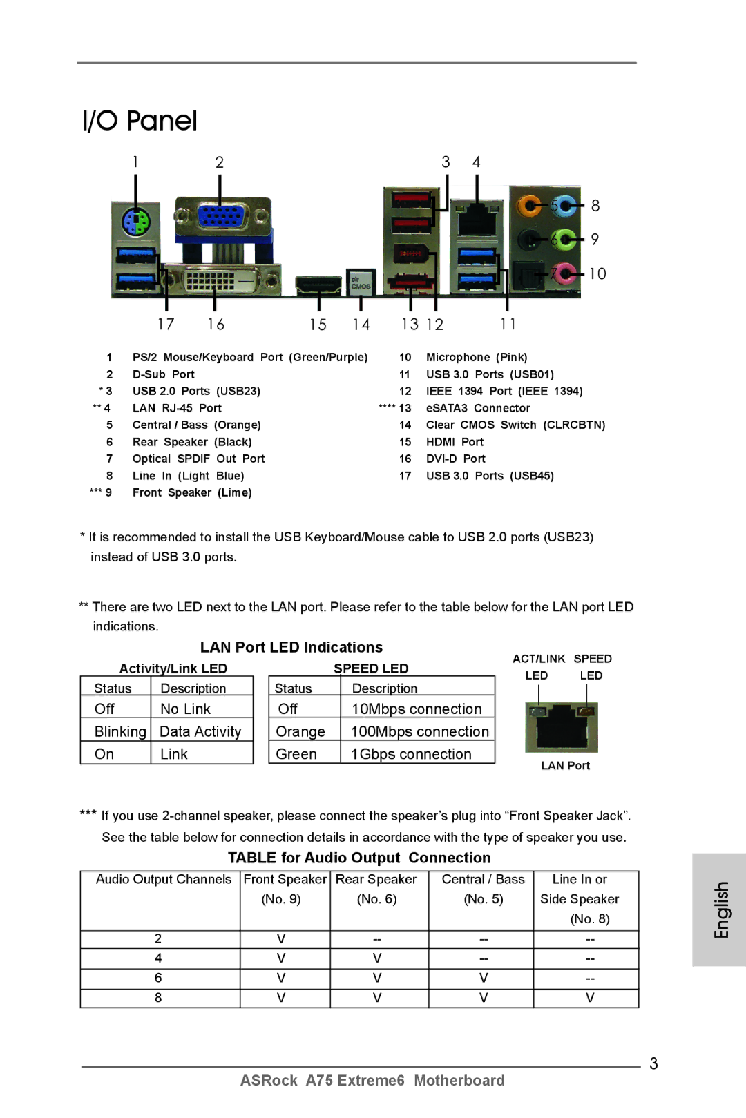
LAN Port LED Indications
Off No Link Blinking Data Activity
Table for Audio Output Connection
English
Introduction
Package Contents
English Specifications
USB
Connector
Audio
Rear Panel I/O
Support CD
Smart Switch
Bios Feature
Unique Feature
FCC, CE, Whql
Certifications
English
English
Pre-installation Precautions
Installation
Installation of CPU Fan and Heatsink
CPU Installation
Dual Channel Memory Configurations
English Installation of Memory Modules Dimm
Installing a Dimm
Installing an expansion card
English Expansion Slots PCI and PCI Express Slots
Pcie Slots
English
CrossFire Bridge
Installing Three CrossFireXTM-Ready Graphics Cards
CrossFireTM Bridge
For Windows 7 / VistaTM OS
Driver Installation and Setup
Install the required drivers to your system
For Windows XP OS
English
AMD Dual Graphics Operation Guide
Enjoy the benefit of AMD Dual Graphics
What does an AMD Dual Graphics system include?
AMD Vision Engine Control Center
Dual Monitor and Surround Display Features
Dual Monitor Feature
Sub port DVI-D port
For Windows XP / XP 64-bit OS
Surround Display Feature
What is HDCP?
For Windows 7 / 7 64-bit / VistaTM / VistaTM 64-bit OS
Hdcp Function
ASRock Smart Remote Installation Guide
USB 2.0 header 9-pin, blue CIR header 4-pin, white
CIR sensors in different angles
Clear Cmos Jumper
Jumpers Setup
Jumper
Description
Onboard Headers and Connectors
Ports on the I/O panel, there
USB 2.0 Headers Besides two default USB
USB 3.0 Header Besides four default USB
Optional wireless transmitting
System Panel Header
Several system front panel
Functions
Cable to the connector
To the fan connectors
Match the black wire to
CPU Fan Connectors
Serial port Header
ATX Power Connector
Supply to this connector
ATX 12V Power Connector
Projector/LCD devices. Please
Hdmispdif Header Hdmispdif header, providing
Spdif audio output to Hdmi
Connect Hdmi Digital TV
Smart Switches
Status Code Description
12 Dr. Debug
English
English
English
Install Windows XP / XP 64-bit OS on your system
Driver Installation Guide
Installing Windows XP / XP 64-bit Without RAID Functions
\ RAID Installation Guide
English
Bios Information
Kartoninhalt
Deutsch
Spezifikationen
USB3.0
Anschlüsse
An der
Rückseite
Support-CD
Einzigartige
Eigenschaft Siehe Vorsicht
FCC, CE, Whql
Zertifizierungen
Deutsch
Deutsch
Sicherheitshinweise vor der Montage
Installation des CPU-Lüfters und des Kühlkörpers
Deutsch CPU Installation
Installation der Speichermodule Dimm
Dual-Kanal-Speicherkonfigurationen
Blau Weiß Bestückt
Einsetzen eines DIMM-Moduls
Erweiterungssteckplätze PCI- und PCI Express-Slots
Einbau einer Erweiterungskarte
PCI Express-Slots
Bedienungsanleitung für AMD duale Grafikkarten
Polig, weiß
ASRock Smart Remote Schnellinstallationsanleitung
Polig, blau
CIR-Header
Nur gelöscht werden, wenn die CMOS-Batterie entfernt wird
Einstellung der Jumper
Jumper Einstellun Beschreibung
Cmos löschen
AnschlussBeschreibung
Anschlüsse
Header an diesem
USB 3.0-Header Neben vier Standard-USB
Ports am E/A-Panel
Befindet sich ein USB
System Panel-Header Dieser Header unterstützt
Mehrere Funktion der
Systemvorderseite
Mit den Lüfteranschlüssen
Gehäuselautsprecher-Header Schließen Sie den
Diesen Header an
Gehäuse- und Stromlüfteranschlüsse
ATX 12V Anschluss Bitte schließen Sie an diesen
CPU-Lüfteranschluss
ATX-Netz-Header Verbinden Sie die ATX
Header
Unterstützen
IEEE-1394 Header
Header wird verwendet, um
Ein COM-Anschlussmodul zu
Schnellschalter
Deutsch Debug-LED
Treiberinstallation
Deutsch
BIOS-Information
Français
Contenu du paquet
Français Spécifications
LED Vitesse
Panneau arrière
CD d’assistance
Connecteurs
Interrupteur
Rapide
Système
Surveillance
Français
Français
Précautions à observer avant l’installation
Installation du ventilateur et du dissipateur
Installation du CPU
Français Installation des modules m émoire Dimm
Configurations de Mémoire à Canal Double
Slot Bleu Slot Blanc Occupé
Installation d’un module Dimm
Installation d’une carte d’extension
Français Slot d’extension Slots PCI et Slots PCI Express
Slots Pcie
Guide d’utilisation de AMD Dual Graphics
Télécommande intelligente ASRock Guide dinstallation rapide
Embase USB 2.0 9 broches, bleue Embase CIR Broches, blanche
Capteurs CIR à différents angles
Réglage des cavaliers
Le cavalier Description
Effacer la Cmos
En-têtes et Connecteurs sur Carte
Connecteurs Série ATA3
En-tête USB
USB 3.0 sur la carte mère
En-tête USB En plus des quatre ports
USB 3.0 par défaut sur le
Panneau E/S, il y a une barrette
En-tête du panneau système Cet en-tête permet d’utiliser
Plusieurs fonctions du
Panneau système frontal
Connecteur du ventilateur De l’UC
En-tête du haut-parleur Veuillez connecter le De châssis
Cet en-tête
Le fil noir à la broche de terre
Tête
Installation de ventilateur à 3 broches
En-tête d’alimentation ATX Veuillez connecter l’unité
’alimentation ATX sur cet en
Fournissant une sortie audio
Header de Ieee
Utilisée pour prendre en charge
Un module de port COM
LED de débogage
Interrupteur rapides
Guide d’installation des pilotes
Installation de Windows XP / XP 64-bit sans fonctions
\ RAID Installation Guide Guide d’installation RAID
Français
Informations sur le Bios Informations sur le CD de support
Italiano
Contenuto della confezione
Un I/O Shield
Specifiche
Posteriore
Pannello
CD di
Connettori
Interruttore
Rapido
Compatibi
Lità SO
Certificazioni
Italiano
100
101
Precauzioni preinstallazione
Italiano Installazione del processore
Installazione della ventolina e del dispersore di calore
102
Popolato
Installazione dei moduli di memoria Dimm
Configurazioni Dual Channel Memory
103
104
Italiano Installare una Dimm
Installare una scheda di espansione
Slot di espansione Slot PCI ed Slot PCI Express
105
106
Guida al funzionamento di AMD Dual Graphics
Sensori CIR su angolazioni diverse
ASRock Smart Remote Guida allinstallazione rapida
107
Connettore USB 2.0 9 pin, blu Connettore CIR 4 pin, bianco
Jumper Settaggio del Jumper
Setup dei Jumpers
Resettare la Cmos
108
Cavo audio da 3,5 mm
Collettori e Connettori su Scheda
109
Connettori Serial ATA3
110
111
Collettore pannello di sistema
Diverse funzioni di sistema
112
Connettore ATX 12 Collegare un alimentatore ATX
113
Connettore alimentazione ATX Collegare la sorgente
Connettore
114
115
Guida installazione del driver
Interruttori rapidi
LED di debug
116
Installazione di Windows XP / XP 64 bit senza funzioni
\ RAID Installation Guide Guida all’installazione RAID
Passo Installazione di Windows XP / XP 64-bit sul sistema
117
Español
Contenido de la caja
118
119
Especificación
Trasero
120
Entrada/Salida
De Panel
121
122
Monitor Hardware
Certificaciones
123
124
125
Precaución de Pre-instalación
Paso 4. Encierre el zócalo bajando la palanca
Instalación de Procesador
Instalación del Ventilador y el Radiador de la CPU
126
Configuraciones de Memoria de Doble Canal
Instalación de Memoria
127
128
Instalación de una Dimm
Ranura PCI Express
Ranuras de Expansión ranuras PCI y ranuras PCI Express
Instalación de Tarjetas de Expansión
129
130
Manual del usuario de AMD gráfica dual
Sensores CIR en diferentes ángulos
131
Limpiar Cmos
Setup de Jumpers
Jumper Setting
132
Cable de audio de 3,5 mm
Cabezales y Conectores en Placas
133
Conexiones de serie ATA3
134
135
Cabezal de panel de sistema
Sistema
136
Necesario conectar este
Conector de ATX 12V power Tenga en cuenta que es
137
Cabezal de alimentación ATX Conecte la fuente de
138
Conmutadores rápidos
Indicador LED de depuración
139
Español 12 Guía de instalación del controlador
Instalación de Windows XP / XP 64 bits sin Funciones
140
141
142
Bios Información Información de Software Support CD
Комплектность
Русский
143
144
Русский Спецификации
145
146
Внимание
147
148
149
150
Меры предосторожности
Установка процессора
Установка вентилятора и радиатора ЦП
151
Русский Установка модулей памяти Dimm
152
Синий Белый Заполнено
153
Установка модуля Dimm
Русский Гнезда расширения PCI и PCI Express
Установка карты расширения
154
155
CIR-датчика под различными углами
Установка перемычек
157
Перемычка Установка Описание
158
Колодки и разъемы на плате
159
Pled индикатор питания системы
Reset кнопка сброса
160
Pwrbtn кнопка питания
Hdled индикатор активности жесткого диска
161
162
Контакты 1-3 подключены
Наряду с Булавкой 1 и Прикрепите
163
164
10 Быстрое переключение
11 Режим отладки
12 Указания по установке драйверов
ШАГ 2. Установите на свою систему Windows XP / XP 64-bit
165
166
Информация о Bios
Paket İçindekiler
Türkçe
167
168
Özellikler
Konektör
169
Ses
Arka Panel
170
Uyari
171
172
173
174
Kurulum Öncesi Önlemler
Aşağı Bastırın ve Soket Mandalını Kilitleyin
CPUnun Takılması
CPU Fanı ve Isı Emicisinin Takılması
175
Beyaz Yuva Mavi Yuva
Bellek Modüllerinin Dimm Takılması
176
Çift Kanallı Bellek Yapılandırmaları
177
Bir Dimm takma
Genişletme Yuvaları PCI ve PCI Express Yuvaları
Genişletme kartı takma
178
179
Dual Graphics Çalışma Kılavuzu
Farklı açılarda 3 CIR sensörü
ASRock Akıllı Uzaktan Kumanda Hızlı Kurulum Kılavuzu
180
USB 2.0 başlığı 9 pimli, mavi CIR başlığı Pimli, beyaz
CMOS’u temizleme
Jumperların Ayarı
181
Jumper Ayar
USB 2.0 Fişleri
Yerleşik Fişler ve Konektörler
182
Seri ATA3 Konektörler SATA30 bkz. s.2, No
183
184
Sistem Paneli Fişi
Işlevini barındırır
Fanına bu konektöre bağlayın
185
CPU Fan Konektörü
Lütfen fan kablolarını CPU
ATX 12V Güç Konektörü
186
ATX Güç Konektörü
Lütfen bir ATX güç kaynağını bu konektöre bağlayın
10 Akıllı Anahtarlar
11 Dr. Debug
187
\ RAID Yükleme Kılavuzu
12 Sürücü Yükleme Kılavuzu
Windows XP / XP 64-biti RAID İşlevleri Olmadan Yükleme
188
189
190
Bios Bilgileri Yazılım Destek CD’si bilgileri
191
제품소개
고급 V8 + 2 전원 위상 디자인
192
플랫폼 ATX 폼 팩터 12.0X 9.6, 30.5 X 24.4 cm
소켓 FM1 100W 프로세서 지원
193
194
195
196
197
설치전의 예방조치
198
메인보드의 셋팅을 변경하거나 메인보드에 부품을 설치하기 전에 아 래의 안전 수칙을 따라 주세요
199
CPU 설치
200
하얀색 슬롯
장착됨
201
메모리의 설치
202
확장 슬롯 PCI 슬롯 , PCI Express 슬롯
203
CrossFireXTM, 3-Way CrossFireXTM 및 Quad CrossFireXTM 사용 설명서
204
ASRock Smart Remote 간편 설치 설명서
점퍼세팅
205
Cmos 초기화
206
207
것입니다
208
시스템 콘넥터 콘넥터는 시스템 전면 패
널기능을 지원하기 위한
209
210
211
Cmos 삭제 스위치는 빠른 스위 치로서 , 사용자가 Cmos 값을 빠르게 삭제할 수 있습니다
212
전원 스위치는 빠른 스위치로서 , 사용자가 시스템을 빠르게 켜거 나 끌 수 있습니다 리셋 스위치
리셋 스위치는 빠른 스위치로서 , 사용자가 시스템을 빠르게 리셋 할 수 있습니다 Cmos 삭제 스위치
213
RAID 기능이 지원되지 않는 Windows XP / XP 64 비트
214
215
시스템 바이오스 정보 소프트웨어 지원 CD 정보
シリアル ATA Sata データケーブル(オプション) 3.5mm オーディオケーブル(オプション)
パッケージ内容
日本語
216
217
218
219
220
ASRock Instant Flash は、Flash ROM(フラッシュ ROM)に組み込ま
221
222
インストレーションを行う前の注意事項
223
IC には触れないように部品の角を持ちます。
CPU インストレーション
CPU ファンとヒートシンクのインストール
224
実装済み
メモリーモジュール Dimm 取り付け
225
デュアルヱャンネルメモリーコンフィギュレーション
Dimm スロットが用意されています。
226
拡張スロット(PCI スロット、PCI Express スロット)
拡張カードの装着
227
228
AMD Dual Graphics 操作ガイド
229
ASRock Smart Remote クイック取り付けガイド
ジャンパ設定
オンボードのヘッダとコネクタ類
230
できます。
231
フロントオーディオパネルコネクタ GND
232
シャーシに付いている電源スイッチ、リセットスイッチ、システムステータ
233
アースピンに接続してください。
234
ATX 12V コネクタ
235
トをインストールする
10 クイックスイッヱ
11 デバッグ LED
12 ドライバインストールガイド
トールする
ビットをインストールする
RAID 機能を搭載しない Windows XP / XP 64-bit ビット
をインストールする
238
BIN フォルダにある ASSETUP.EXE をダブルクリックすることにより、メインメニュウが 立ち上がります。
239
簡體中文
240
主板規格
241
242
243
警告!
244
245
安全防范
CPU 安裝
安裝 CPU 風扇和散熱片
246
2 No.7)或者在雙通道 B 安裝同樣的 DDR3 Dimm 內存條(DDR3A2 和 DDR3B2;
247
248
安裝步驟:
249
擴展插槽 PCI 和 PCI Express 插槽
CrossFireXTM, 3-Way CrossFireXTM 和 Quad CrossFireXTM 操作指南
AMD 雙顯卡操作指南
250
251
ASRock 智能遙控器快速安裝指南
跳線設置
252
清除 Cmos
253
板載接頭和接口
254
板功能。
255
GND可以方便連接音頻設備。
系統面板接頭
CPU 風扇接頭
256
257
10 快速開關
11 調試 LED
258
259
Using SATA3 HDDs without NCQ function 使用不帶 NCQ 功能的 SATA3 硬盤
12 驅動程序安裝指南
14.1 在不帶 RAID 功能的系統上安裝 Windows XP / XP 64 位元
接口。
260
VistaTM 64 位元,請按下面的步驟操作。
步驟 1 設置 UEFI。
本主板支持各種微軟視窗操作系統:Microsoft Windows 7/7 64 位元 /VistaTM
261
262
電子信息產品污染控制標示
263
繁體中文
264
繁體中文 主機板規格
265
266
267
268
269
安全防範
270
271
記憶體安裝
、 將記憶體平穩地插入插槽直至兩端卡子迅速而完全地歸位以及記憶體完 全就位。
272
273
擴充插槽 PCI 和 PCI Express 插槽
274
CrossFireXTM,3-Way CrossFireXTM 和 Quad CrossFireXTM 操作指南
275
ASRock 智慧型遙控器快速安裝指南
276
277
SATA3 接口。 5mm 音訊線
路輸入 Line-in 連接埠。
278
前置音效接頭
279
電源指示燈接頭
280
序列埠
281
ATX 12V 電源接口
致供電故障。
11 偵錯 LED
12 驅動程式安裝指南
282
283
如果您只想在不帶 RAID 功能的 SATA3 硬碟上安裝 Windows 7 / 7 64 位元 / VistaTM
XP / XP 64 位元操作系統。
接頭。
284
285
支援光碟訊息
286
Installing OS on a HDD Larger Than 2TB