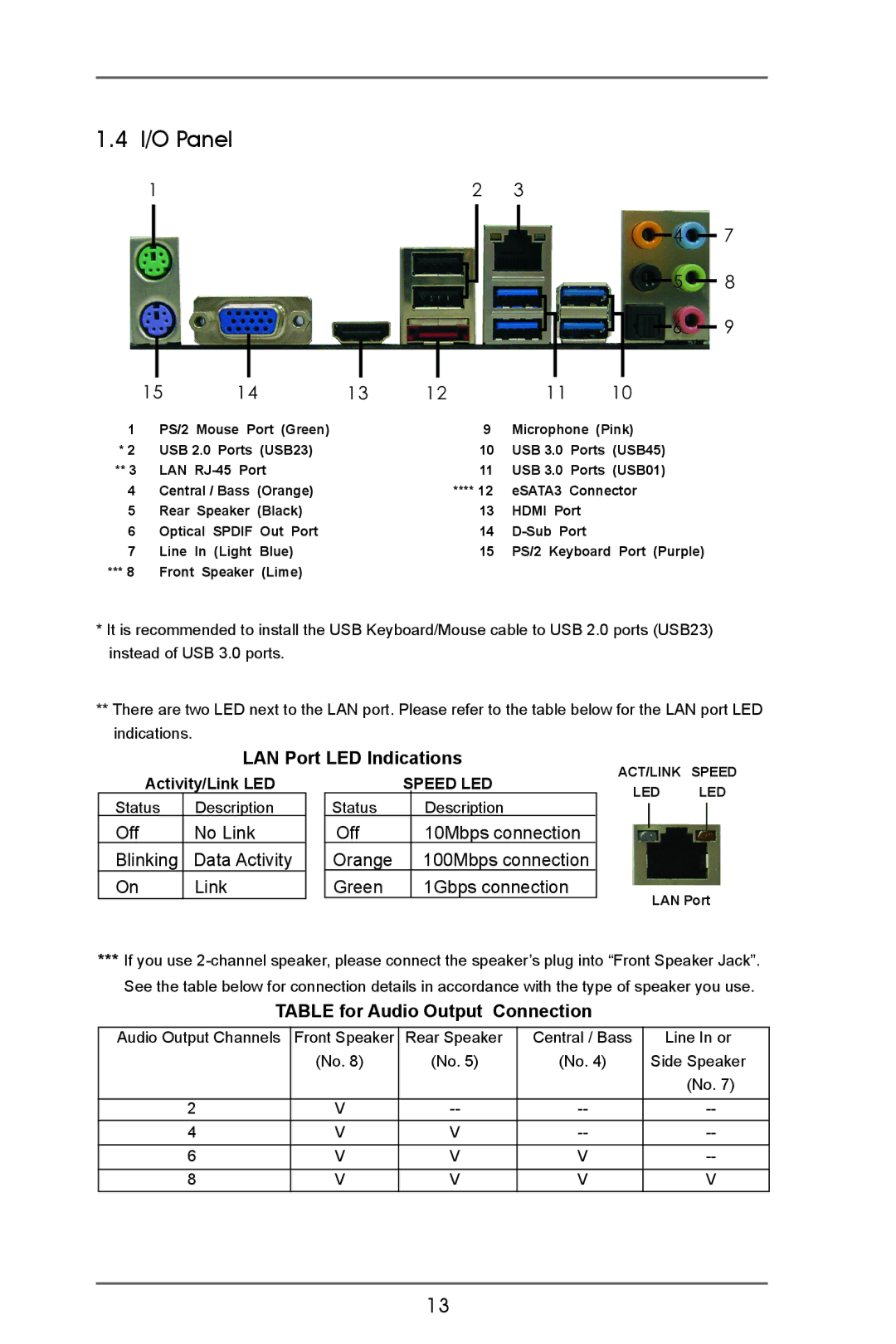
1.4 I/O Panel |
|
|
|
|
|
|
|
|
|
|
|
|
|
|
|
|
|
|
|
|
| ||
1 |
|
| 2 | 3 |
|
|
|
|
|
|
|
|
|
|
|
|
|
| |||||
|
|
|
|
|
|
|
|
|
|
|
|
|
|
| 4 |
|
| 7 | |||||
|
|
|
|
|
|
|
|
|
|
|
|
|
| ||||||||||
|
|
|
|
|
|
|
|
|
|
| |||||||||||||
|
|
|
|
|
|
|
|
|
|
|
|
|
|
|
| 5 |
|
|
| 8 | |||
|
|
|
|
|
|
|
|
|
|
|
| ||||||||||||
|
|
|
|
|
|
|
|
|
|
| |||||||||||||
|
|
|
|
|
|
|
|
|
|
|
|
|
|
|
|
|
| 6 |
|
| 9 | ||
|
|
|
|
|
|
|
|
|
|
|
|
|
|
|
|
|
|
| |||||
|
|
|
|
|
|
|
|
|
|
|
|
|
|
|
|
|
|
|
|
|
|
|
|
| 15 | 14 | 13 | 12 |
| 11 | 10 |
1 | PS/2 Mouse Port (Green) |
|
| 9 | Microphone (Pink) | ||
* 2 | USB 2.0 Ports (USB23) |
|
| 10 | USB 3.0 | Ports (USB45) | |
** 3 | LAN |
|
| 11 | USB 3.0 | Ports (USB01) | |
4 | Central / Bass (Orange) |
|
| **** 12 | eSATA3 Connector | ||
5 | Rear Speaker (Black) |
|
| 13 | HDMI Port | ||
6 | Optical SPDIF Out Port |
|
| 14 | |||
7 | Line In (Light Blue) |
|
| 15 | PS/2 Keyboard Port (Purple) | ||
***8 Front Speaker (Lime)
* It is recommended to install the USB Keyboard/Mouse cable to USB 2.0 ports (USB23) instead of USB 3.0 ports.
**There are two LED next to the LAN port. Please refer to the table below for the LAN port LED indications.
LAN Port LED Indications
ACT/LINK SPEED
Activity/Link LED
Status | Description |
Off | No Link |
Blinking | Data Activity |
On | Link |
| SPEED LED | |
Status |
| Description |
Off |
| 10Mbps connection |
Orange |
| 100Mbps connection |
Green |
| 1Gbps connection |
LED LED
LAN Port
***If you use
TABLE for Audio Output Connection
Audio Output Channels | Front Speaker | Rear Speaker | Central / Bass | Line In or |
| (No. 8) | (No. 5) | (No. 4) | Side Speaker |
|
|
|
| (No. 7) |
|
|
|
|
|
2 | V | |||
4 | V | V | ||
6 | V | V | V | |
|
|
|
|
|
8 | V | V | V | V |
13