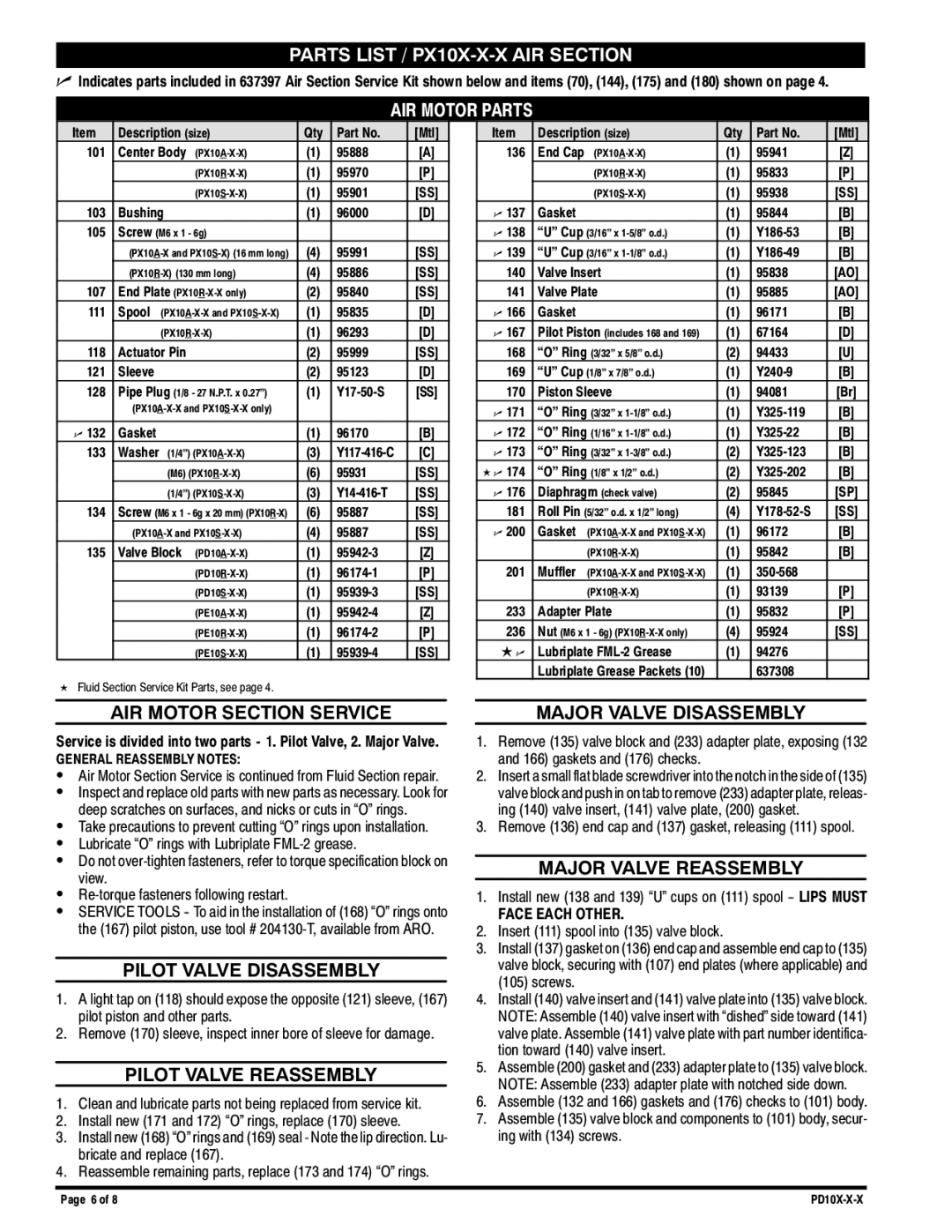
PARTS LIST / PX10X-X-X AIR SECTION

nIndicates parts included in 637397 Air Section Service Kit shown below and items (70), (144), (175) and (180) shown on page 4.

AIR MOTOR PARTS

Item

Description (size)

Qty

Part No.

[Mtl]

101

Center Body

(PX10A-X-X)

(1)

95888

[A]


(PX10R-X-X)

(1)

95970

[P]


(PX10S-X-X)

(1)

95901

[SS]

103

Bushing


(1)

96000

[D]

105

Screw (M6 x 1 - 6g)


(PX10A-X and PX10S-X) (16 mm long)

(4)

95991

[SS]


(PX10R-X) (130 mm long)

(4)

95886

[SS]

107

End Plate (PX10R-X-X only)

(2)

95840

[SS]

111

Spool

(PX10A-X-X and PX10S-X-X)

(1)

95835

[D]


(PX10R-X-X)

(1)

96293

[D]

118

Actuator Pin


(2)

95999

[SS]

121

Sleeve


(2)

95123

[D]

128

Pipe Plug (1/8 - 27 N.P.T. x 0.27”)

(1)

Y17-50-S

[SS]


(PX10A-X-X and PX10S-X-X only)


n 132

Gasket


(1)

96170

[B]

133

Washer

(1/4”) (PX10A-X-X)

(3)

Y117-416-C

[C]


(M6) (PX10R-X-X)

(6)

95931

[SS]


(1/4”) (PX10S-X-X)

(3)

Y14-416-T

[SS]

134

Screw (M6 x 1 - 6g x 20 mm) (PX10R-X)

(6)

95887

[SS]


(PX10A-X and PX10S-X-X)

(4)

95887

[SS]

135

Valve Block

(PD10A-X-X)

(1)

95942-3

[Z]


(PD10R-X-X)

(1)

96174-1

[P]


(PD10S-X-X)

(1)

95939-3

[SS]


(PE10A-X-X)

(1)

95942-4

[Z]


(PE10R-X-X)

(1)

96174-2

[P]


(PE10S-X-X)

(1)

95939-4

[SS]

KFluid Section Service Kit Parts, see page 4.

Item

Description (size)

Qty

Part No.

[Mtl]

136

End Cap

(PX10A-X-X)

(1)

95941

[Z]


(PX10R-X-X)

(1)

95833

[P]


(PX10S-X-X)

(1)

95938

[SS]

n 137

Gasket


(1)

95844

[B]

n 138

“U” Cup (3/16” x 1-5/8” o.d.)

(1)

Y186-53

[B]

n 139

“U” Cup (3/16” x 1-1/8” o.d.)

(1)

Y186-49

[B]

140

Valve Insert

(1)

95838

[AO]

141

Valve Plate

(1)

95885

[AO]

n 166

Gasket


(1)

96171

[B]

n 167

Pilot Piston (includes 168 and 169)

(1)

67164

[D]

168

“O” Ring (3/32” x 5/8” o.d.)

(2)

94433

[U]

169

“U” Cup (1/8” x 7/8” o.d.)

(1)

Y240-9

[B]

170

Piston Sleeve

(1)

94081

[Br]

n 171

“O” Ring (3/32” x 1-1/8” o.d.)

(1)

Y325-119

[B]

n 172

“O” Ring (1/16” x 1-1/8” o.d.)

(1)

Y325-22

[B]

n 173

“O” Ring (3/32” x 1-3/8” o.d.)

(2)

Y325-123

[B]

K n 174

“O” Ring (1/8” x 1/2” o.d.)

(2)

Y325-202

[B]

n 176

Diaphragm (check valve)

(2)

95845

[SP]

181

Roll Pin (5/32” o.d. x 1/2” long)

(4)

Y178-52-S

[SS]

n 200

Gasket

(PX10A-X-X and PX10S-X-X)

(1)

96172

[B]


(PX10R-X-X)

(1)

95842

[B]

201

Muffler

(PX10A-X-X and PX10S-X-X)

(1)

350-568


(PX10R-X-X)

(1)

93139

[P]

233

Adapter Plate

(1)

95832

[P]

236

Nut (M6 x 1 - 6g) (PX10R-X-X only)

(4)

95924

[SS]

L n

Lubriplate FML-2 Grease

(1)

94276


Lubriplate Grease Packets (10)


637308


AIR MOTOR SECTION SERVICE

Service is divided into two parts - 1. Pilot Valve, 2. Major Valve.

GENERAL REASSEMBLY NOTES:

SAir Motor Section Service is continued from Fluid Section repair.

SInspect and replace old parts with new parts as necessary. Look for deep scratches on surfaces, and nicks or cuts in “O” rings.

STake precautions to prevent cutting “O” rings upon installation.

SLubricate “O” rings with Lubriplate FML-2 grease.

SDo not over-tighten fasteners, refer to torque specification block on view.

SRe-torque fasteners following restart.

SSERVICE TOOLS -- To aid in the installation of (168) “O” rings onto the (167) pilot piston, use tool # 204130-T, available from ARO.

PILOT VALVE DISASSEMBLY

1.A light tap on (118) should expose the opposite (121) sleeve, (167) pilot piston and other parts.

2.Remove (170) sleeve, inspect inner bore of sleeve for damage.

PILOT VALVE REASSEMBLY

1.Clean and lubricate parts not being replaced from service kit.

2.Install new (171 and 172) “O” rings, replace (170) sleeve.

3.Install new (168) “O” rings and (169) seal - Note the lip direction. Lu- bricate and replace (167).

4.Reassemble remaining parts, replace (173 and 174) “O” rings.

MAJOR VALVE DISASSEMBLY

1.Remove (135) valve block and (233) adapter plate, exposing (132 and 166) gaskets and (176) checks.

2.Insert a small flat blade screwdriver into the notch in the side of (135) valve block and push in on tab to remove (233) adapter plate, releas- ing (140) valve insert, (141) valve plate, (200) gasket.

3.Remove (136) end cap and (137) gasket, releasing (111) spool.

MAJOR VALVE REASSEMBLY

1.Install new (138 and 139) “U” cups on (111) spool -- LIPS MUST

FACE EACH OTHER.

2.Insert (111) spool into (135) valve block.

3.Install (137) gasket on (136) end cap and assemble end cap to (135) valve block, securing with (107) end plates (where applicable) and (105) screws.

4.Install (140) valve insert and (141) valve plate into (135) valve block. NOTE: Assemble (140) valve insert with “dished” side toward (141) valve plate. Assemble (141) valve plate with part number identifica- tion toward (140) valve insert.

5.Assemble (200) gasket and (233) adapter plate to (135) valve block. NOTE: Assemble (233) adapter plate with notched side down.

6.Assemble (132 and 166) gaskets and (176) checks to (101) body.

7.Assemble (135) valve block and components to (101) body, secur- ing with (134) screws.

Page 6 of 8

PD10X-X-X

Page 6
Image 6
Ingersoll-Rand PD10X-X-X, PE10X-X-X manual Parts List / PX10X-X-X AIR Section

PD10X-X-X, PE10X-X-X specifications

Ingersoll-Rand has long been a leader in the manufacturing of high-quality air compressors, and the PE10X-X-X and PD10X-X-X models represent some of their most innovative offerings. These models are designed to meet the demands of various industrial applications, delivering robust performance and exceptional reliability.

The PE10X-X-X series stands out with its unique combination of power and efficiency. It features a reliable and durable rotary screw design, which allows for continuous operation with minimal maintenance. The modular design of the PE10X-X-X ensures easy accessibility for servicing, reducing downtime and enhancing productivity. Additionally, this model incorporates advanced cooling systems that maintain optimal performance, even under the toughest working conditions.

On the other hand, the PD10X-X-X series is engineered with an emphasis on versatility and user-friendly operation. This model is equipped with an innovative variable speed drive technology, which allows users to adjust the compressor's output according to their specific air demands. This not only optimizes energy consumption but also contributes to significant cost savings over time. The PD10X-X-X also features a state-of-the-art control system that provides real-time monitoring and diagnostics, enabling operators to make informed decisions regarding performance and maintenance.

Both models boast integrated soundproofing technologies that ensure quiet operation, making them suitable for use in environments where noise levels should be minimized. They are also designed with environmentally friendly refrigerants, adhering to industry standards for sustainability.

Ingersoll-Rand prides itself on the reliability of its compressors, and both the PE10X-X-X and PD10X-X-X models are no exception. Engineered for durability, these compressors are fitted with high-quality components that ensure consistent performance over an extended lifespan. Additionally, they come equipped with advanced filtration systems that help maintain clean air distribution, thus protecting downstream equipment.

In summary, the Ingersoll-Rand PE10X-X-X and PD10X-X-X models exemplify cutting-edge technology and user-centric design. With features such as rotary screw design, variable speed drive technology, advanced control systems, and soundproofing, these compressors deliver optimal efficiency and reliability for demanding industrial applications. Whether you need a high-performance solution for continuous operation or a versatile unit that adapts to varying demands, these models offer outstanding capabilities to meet the needs of modern businesses.