Chassis Speaker Header | 1 |
|
|
|
| ||
|
| SPEAKER | |
|
| DUMMY | |
(see p.14 No. 16) | +5V DUMMY | ||
|
|
| |
Please connect the chassis speaker to this header.
Power LED Header | Please connect the chassis |
power LED to this header to | |
(see p.14 No. 29) | indicate system power status. |
| The LED is on when the system |
| is operating. The LED keeps |
| blinking in S1 state. The LED is |
| off in S3/S4 state or S5 state |
| (power off). |
Chassis and Power Fan Connectors
(see p.14 | No. 20) | GND |
+12V | ||
|
| CHA_FAN_SPEED |
|
| FAN_SPEED_CONTROL |
|
| GND |
+12V | ||
CHA_FAN_SPEED | ||
(see p.14 | No. 6) |
|
|
| GND |
+12V | ||
CHA_FAN_SPEED | ||
(see p.14 | No. 24) |
|
|
| +12V |
GND PWR_FAN_SPEED | ||
(see p.14 | No. 10) |
|
Please connect the fan cables to the fan connectors and match the black wire to the ground pin. CHA_FAN1/2/3 fan speed can be controlled through UEFI or AXTU.
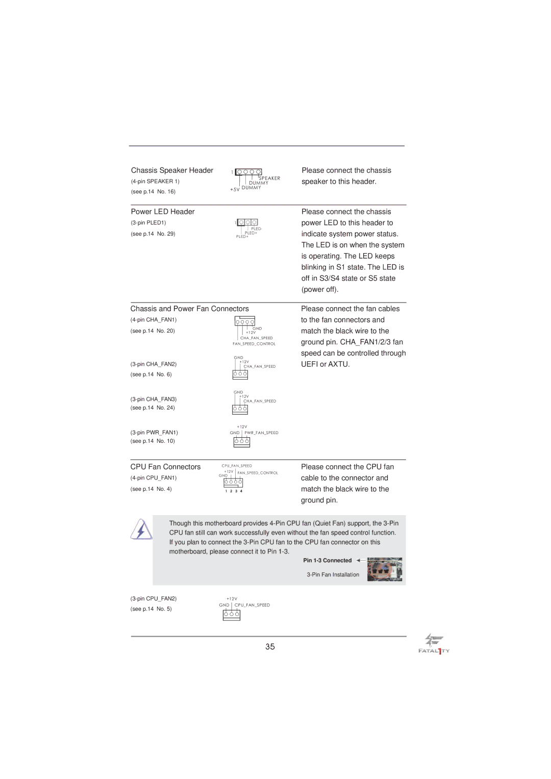
CPU Fan Connectors
(see p.14 No. 4)
CPU_FAN_SPEED
+12V ![]() FAN_SPEED_CONTROL GND
FAN_SPEED_CONTROL GND ![]()
1 2 3 4
Please connect the CPU fan cable to the connector and match the black wire to the ground pin.
Though this motherboard provides
Pin
+12V | |
(see p.14 No. 5) | GND CPU_FAN_SPEED |
|
35