Fatal1ty Story
English
LIVIN’ Large
Disclaimer
Copyright Notice
X79
Motherboard Layout
Table for Audio Output Connection
Panel
LAN Port LED Indications
Off No Link Blinking Data Activity
English
Introduction
Package Contents
English Specifications
Connector
Smart Switch
USB3.0
Hardware
Bios Feature
Unique Feature
Support CD
English
English
English
CPU Installation
Pre-installation Precautions
Pin1
English
With fan operation or contact other components
Installation of CPU Fan and Heatsink
Installing a Dimm
English Installation of Memory Modules Dimm
Expansion Slots PCI and PCI Express Slots
Pcie Slot Configurations
Installing an expansion card
Requirements
ASRock SLIBridge3S Card
Installing Three SLITM-Ready Graphics Cards
Two Goldfingers
ASRock 3-Way SLI Bridge Card
ASRock SLIBridge Cards An ASRock SLIBridge3S Card
Installing Four SLITM-Ready Graphics Cards
Driver Installation and Setup
For Windows XP / XP 64-bit OS For Slitm mode only
Double-click Nvidia Settings icon on your Windows taskbar
Select Nvidia Control Panel tab
Follow steps a to E on
English
CrossFire Bridge
CrossFireTM Bridge
Installing Three CrossFireXTM-Ready Graphics Cards
Installing Four CrossFireXTM-Ready Graphics Cards
ATI Catalyst Control Center
Install the required drivers to your system
For Windows XP OS
For Windows 7 / VistaTM OS
\ Surround Display Information
Surround Display Feature
ASRock Smart Remote Installation Guide
USB 2.0 header 9-pin, black CIR header 4-pin, gray
CIR sensors in different angles
ASRock XFast Charger Operation Guide
Clear Cmos Jumper
Jumpers Setup
Jumper
Description
Onboard Headers and Connectors
Three USB 2.0 headers on this
USB 2.0 Headers Besides six default USB
USB 3.0 Header Besides four default USB
Optional wireless transmitting
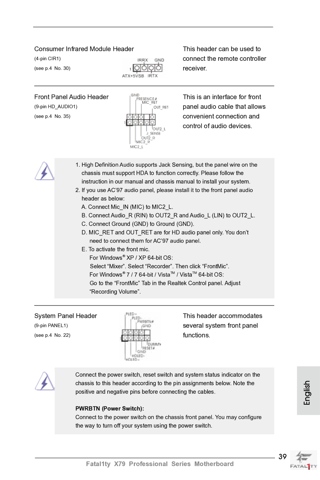
Front Panel Audio Header This is an interface for front
Connect the remote controller
Consumer Infrared Module Header This header can be used to
Receiver
Power off
Power LED Header Please connect the chassis
Power LED to this header to
Indicate system power status
ATX Power Connector Please connect an ATX power
CPU Fan Connectors Please connect the CPU fan
Cable to the connector
Match the black wire to
Motherboard. This Ieee
Port on the I/O panel, there
Is one Ieee 1394 header
FRONT1394 on this
Installation Guide of Rear USB 3.0 Bracket
Installation Guide of Front USB 3.0 Panel
Clear the Cmos values
Smart Switches
Status Code Description
13 Dr. Debug
English
English
English
Install Windows XP / XP 64-bit OS on your system
Driver Installation Guide
Installing Windows XP / XP 64-bit Without RAID Functions
\ RAID Installation Guide
Untied Overclocking Technology
Bios Information
Kartoninhalt
Deutsch
Spezifikationen
Anschlüsse
An der
Rückseite
Hardware Monitor
CD d’assistance
Einzigartige
Eigenschaft
Warnung
Zertifizierungen
Deutsch
Deutsch
Deutsch
Einstellung der Jumper
Jumper Einstellun Beschreibung
Cmos löschen
Integrierte Header und Anschlüsse
Anschlussleiste werden zwei
Serial ATA- Sata Stromversorgungskabel
Üblichen USB 2.0-Ports an den
Am Motherboard. Pro USB
Consumer Infrared-Modul-Header Dieser Header kann zum
Infrarot-Modul-Header Dieser Header unterstützt ein
Optionales, drahtloses Sende
Und Empfangs-Infrarotmodul
Diesen Header an
Gehäuselautsprecher-Header Schließen Sie den
Systembetriebsstatus an
Betriebs-LED-Header Bitte schließen Sie die
Betriebs-LED des Gehäuses
Zur Anzeige des
ATX-Netz-Header Verbinden Sie die ATX
Stromversorgung mit diesem
Header
IEEE-1394 Header
IEEE-1394 Header Außer einem vorgegebenem
IEEE-1394 Port auf dem Ein
Ausgabe Paneel, gibt es einen
Installationsanleitung zum USB 3.0-Blech an der Rückwand
Installationsanleitung der USB 3.0-Frontblende
Schnell löschen können
Schnellschalter
Ein Schnellschalter, mit dem
Benutzer die CMOS-Werte
BIOS-Information
Français
Contenu du paquet
Spécifications Français
Panneau arrière
USB
Connecteurs
Unique
Interrupteur
Rapide
Caractéristique
Système
Surveillance
Français
Français
Français
Réglage des cavaliers
Le cavalier Description
Effacer la Cmos
En-têtes et Connecteurs sur Carte
Embases USB 2.0 sur cette
En-tête USB Côté des six ports
USB 2.0 par défaut sur le
Panneau E/S, il y a trois
Décodeurs, etc
Pour connecter des modules à
Infrarouges grand public
Comme chaînes hi-fi
Alimentazione del sistema. Il
En-tête
LED di accensione Collegare il LED di accensione
Chassi per indicare lo stato di
Tête
En-tête d’alimentation ATX Veuillez connecter l’unité
Sur le panel I/O, il y a un
Connecteur ATX
’alimentation électrique ATX
12V sur ce connecteur
Spdif vers la carte VGA Hdmi
En-tête de port COM Cette en-tête de port COM est
Un module de port COM
Fournissant une sortie audio
Le Guide dinstallation du Support arrière USB
Le Guide d’installation du panneau USB 3.0 frontal
Interrupteur rapides
Informations sur le Bios Informations sur le CD de support
Contenuto della confezione
Italiano
Specifiche
Connettori
Pannello
Posteriore I/O
RAID 0 e RAID 1, delle funzioni NCQ, Ahci e Hot Plug
Caratteristica
Rapido
CD di
Supporto
Certificazioni
XP 64 bit vedi Attenzione
Italiano
Italiano
Setup dei Jumpers
Resettare la Cmos
Jumper Settaggio del Jumper
Collettori e Connettori su Scheda
Intestazioni USB 2.0. Ciascuna
Collettore USB Oltre alle sei porte USB
Predefinite nel pannello I/O, la
Scheda madre dispone di tre
100
101
Collettore casse telaio Collegare le casse del telaio a
Questo collettore
102
Connettore alimentazione ATX Collegare la sorgente
Connettore
103
104
Guida all’installazione del pannello frontale USB
Guida di installazione del supporto USB 3.0 posteriore
105
Velocemente i valori Cmos
Interruttori rapidi
106
Un interruttore rapido che
107
Español
Contenido de la caja
108
109
Especificación
Trasero
110
Entrada/Salida
De Panel
Característica
111
Rápido
CD de soport
Certificaciones
112
113
114
115
Limpiar Cmos
Setup de Jumpers
Jumper Setting
116
117
Cabezales y Conectores en Placas
118
Cabezal de panel de sistema
119
Conveniente de apparatos de
Audio
120
Cabezal del altavoz del chasis
Su cabezal
121
Cabezal de alimentación ATX Conecte la fuente de
122
123
Guía de instalación del Panel frontal USB
Guía de instalación del soporte USB 3.0 posterior
124
125
Conmutadores rápidos
126
Bios Información Información de Software Support CD
127
Введение
128
129
130
Внимание
131
132
133
134
Перемычка Установка Описание
135
136
Колодки и разъемы на плате
137
138
Pled индикатор питания системы
Reset кнопка сброса
139
Pwrbtn кнопка питания
Контакты 1-3 подключены
140
141
142
143
Руководство по установке передней панели USB
144
Быстрое переключение
145
Информация о Bios
146
Türkçe
147
Konektör
148
149
Uyari
150
151
152
153
Jumper Ayar
CMOS’u temizleme
154
155
156
157
158
159
160
Ön USB 3.0 Panelinin Kurulum Kılavuzu
Temizlemelerini sağlayan akıllı
161
Kullanıcıların hızlı bir şekilde
Cmos değerlerini
162
Bios Bilgileri Yazılım Destek CD’si bilgileri
163
제품소개
164
165
166
167
168
169
점퍼세팅
170
Cmos 초기화
171
172
173
174
175
176
전면 USB 3.0 패널의 설치 안내서
후면 USB 3.0 브래킷의 설치 안내서
177
Cmos 삭제 스위치는 빠른 스위 치로서 , 사용자가 Cmos 값을 빠르게 삭제할 수 있습니다
178
전원 스위치는 빠른 스위치로서 , 사용자가 시스템을 빠르게 켜거 나 끌 수 있습니다 리셋 스위치
리셋 스위치는 빠른 스위치로서 , 사용자가 시스템을 빠르게 리셋 할 수 있습니다 Cmos 삭제 스위치
179
시스템 바이오스 정보 소프트웨어 지원 CD 정보
180
ATX フォームファクター 12.0-in x 9.6-in, 30.5 cm x 24.4 cm
シリアル l ATA Sata HDD 用電源変換ケーブル(オプション)
181
182
183
注意 18 を参照
184
185
ます。
186
187
ジャンパ設定
188
オンボードのヘッダとコネクタ類。
USB 2.0 ヘッダ
189
190
Pled システム電源 LED
191
シャーシおよび電源ファンコネクタ
192
ATX 電 12V 源コネクタを接続します。
193
194
前面USB 3.0パネルの取り付けガイド
195
クイックスイッヱ
このマザーボードは Microsoft Windows 7 / 7 64-bit / VistaTM / VistaTM
196
一個后部 USB 3.0 面板
197
198
主板規格
199
200
201
警告!
202
清除 Cmos
203
Serial ATA3 接口 這裡有六組 Serial ATA3
204
Serial ATA2 接口 這裡有四組 Serial ATA2
0Gb/s 的數據傳輸速率。
USB 3.0 擴展接頭
205
Micret 和 Outret 僅用于 HD 音頻面板。您不必將它們連接到 AC’97 音頻面板。 開啟前置麥克風。
206
CPU 風扇接頭
207
CHAFAN1 、CHAFAN2 和
CHAFAN3 支持風扇控制。
208
Hdmispdif 接頭 Hdmispdif 接頭,提供 Spdif
209
210
簡體中文 前部USB 3.0面板安裝指南
211
快速開關
本主板支持各種微軟視窗操作系統:Microsoft Windows 7/7 64 位元 /VistaTM
212
213
電子信息產品污染控制標示
一個後USB 3.0托架
214
ATX 規格 12.0 英吋 x 9.6 英吋 , 30.5 公分 x 24.4 公分
六條 Serial Atasata 數據線 選配
215
216
217
218
219
220
221
USB 3.0 擴充接頭
222
前置音效接頭可以方便連接音效設備。
223
CHAFAN3 支援風扇控制。
224
1394 接口。
225
ATX 12V 電源接口
Ieee 1394 接口之外,這款主機
埠的裝置。
226
227
前USB 3.0面板安裝指南
228
本主板支援各種微軟 Windows 操作系統:Microsoft Windows 7/7 64 位元
229
230
Isi Paket
231
Spesifikasi
232
Penghubung
Beralih
233
234
Installing OS on a HDD Larger Than 2TB
235
Installing OS on a HDD Larger Than 2TB in RAID Mode
Windows VistaTM 64-bit
236
237
Windows 7 64-bit
238