Fatal1ty Story
English
LIVIN’ Large
Copyright Notice
Disclaimer
Published June
Motherboard Layout
Off No Link Blinking
LAN Port LED Indications
Link
Table for Audio Output Connection
English
Introduction
Package Contents
Specifications
Rear Panel I/O
Audio
Smart Switch
Connector
Bios Feature
USB3.0
Support CD
Unique Feature
Hardware
Monitor
English
English
English
Screw Holes
Pre-installation Precautions
Step Orient the CPU with the IHS Inte
CPU Installation
Grated Heat Sink up. Locate Pin1
Two orientation key notches
English
Step Place the heatsink onto the socket. Ensure
To the CPU fan connector on the motherboard
CPUFAN1, see page 4, No or CPU
FAN2, see page 4. No.4
Dual Channel Memory Configuration
Installation of Memory Modules Dimm
Break Notch
Installing a Dimm
Expansion Slots PCI and PCI Express Slots
Installing an expansion card
Requirements
Slitm and Quad Slitm Operation Guide
English
Driver Installation and Setup
For Windows XP / XP 64-bit OS For Slitm mode only
Double-click Nvidia Settings icon on your Windows taskbar
Select Control Panel tab
Select Nvidia Control Panel tab
English
CrossFire Bridge
Installing Three CrossFireXTM-Ready Graphics Cards
CrossFireTM Bridge
For Windows XP OS
Install the required drivers to your system
For Windows 7 / VistaTM OS
ATI Catalyst Control Center
English
Dual Monitor and Surround Display Features
Dual Monitor Feature
DisplayPort Hdmi port
For Windows XP / XP 64-bit OS
Surround Display Feature
What is HDCP?
For Windows 7 / 7 64-bit / VistaTM / VistaTM 64-bit OS
Hdcp Function
Jumper
Jumpers Setup
Description
Clear Cmos Jumper
FDD connector
Onboard Headers and Connectors
Primary IDE connector Black
Connect the black end
USB 2.0 Headers Besides six default USB
Serial ATA Sata Power Cable
USB 3.0 Header Besides six default USB
Optional wireless transmitting
Front Panel Audio Header
System Panel Header
Several system front panel
Power LED to this header to
Power LED Header Please connect the chassis
Indicate system power status
State power off
ATX Power Connector
Supply to this connector
ATX 12V Power Connector Please connect an ATX
Serial port module
Serial port Header
Installation Guide of Rear USB 3.0 Bracket
Installation Guide of Front USB 3.0 Panel
Clear the Cmos values
Smart Switches
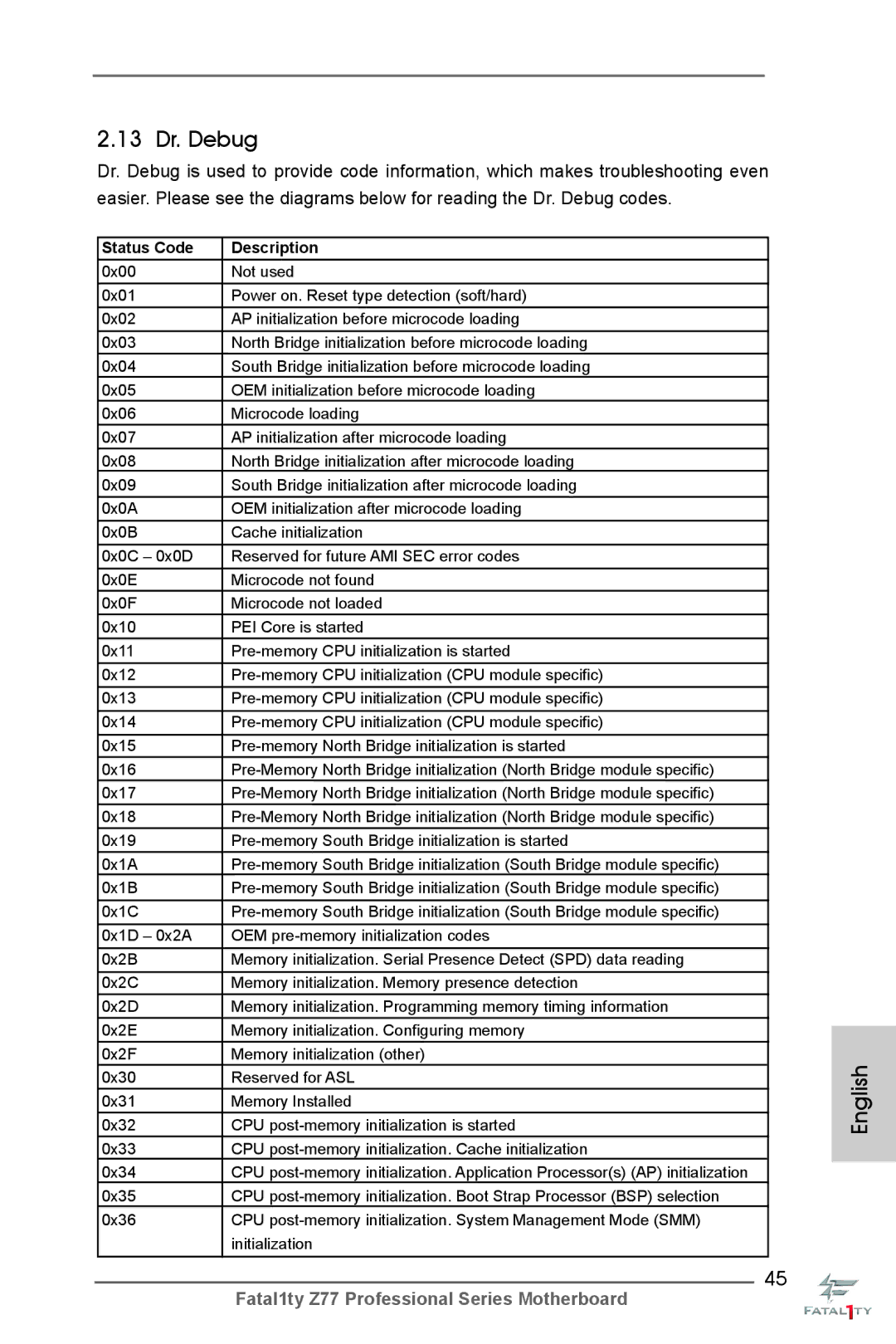
13 Dr. Debug
English
Status Code Description
English
English
English
Installing Windows XP / XP 64-bit Without RAID Functions
Driver Installation Guide
\ RAID Installation Guide
Install Windows XP / XP 64-bit OS on your system
English
Teaming Function Operation Guide
Click Expert Mode
English
English
From Control Panel, double-clickNetwork Connections
Configure the team IP address
Bios Information
Kartoninhalt
Deutsch
Spezifikationen
Anschlüsse
Panel
Ieee 1394 Port Cmos löschen-Schalter mit LED
Unterstützt RAID- RAID 0, RAID 1, RAID 5, RAID 10, Intel
Sata 3-Anschlüsse 6,0 Gb/s durch Intel Z77
Rapid Storage und Intel Smart Response-Technologie
NCQ-, AHCI-und Hot Plug Funktionen
Einzigartige
CD d’assistance
Eigenschaft
Hardware Monitor
Vorsicht
Deutsch
Deutsch
Deutsch
Einstellung der Jumper
Jumper Einstellun Beschreibung
Cmos löschen
Zur Festplatte
Schwarzer Anschluss
Seriell-ATA2-Anschlüsse Diese vier Serial ATA2
SATA2-Verbínder
Der Rückblende anschließen
Festplatte am eSATA3-Port an
Wird der interne SATA3A4
Anschluss deaktiviert
Und Empfangs-Infrarotmodul
Infrarot-Modul-Header Dieser Header unterstützt ein
Der Gehäusevorderseite
System Panel-Header
Diesen Header an
Gehäuselautsprecher-Header Schließen Sie den
CPU-Lüfteranschluss
Stromversorgung mit diesem
ATX-Netz-Header Verbinden Sie die ATX
Header
Stromversorgung an
Wird verwendet, um ein
COM-Anschlussmodul zu
Unterstützen
Schritt
Ein Schnellschalter, mit dem
Schnellschalter
Benutzer die CMOS-Werte
Schnell löschen können
BIOS-Information
Contenu du paquet
Français
Spécifications
VGA sur carte
Pairage Supporte PXE
Panneau arrière
Connecteurs
USB
Rapide
Interrupteur
Caractéristique
Unique
Système
Surveillance
Français
Français
Français
Réglage des cavaliers
Le cavalier Description
Effacer la Cmos
Connecteurs Série ATA3
Connecteurs Série ATA2
Arrière, le connecteur
Port eSATA3 sur le panneau
SATA3A4 interne ne
Fonctionne pas
Et de réception sans fil
En-tête du module infrarouge Cet en-tête supporte un module
En-tête du panneau système Cet en-tête permet d’utiliser
Système frontal
LED di accensione Collegare il LED di accensione
En-tête
Chassi per indicare lo stato di
Alimentazione del sistema. Il
Tête
En-tête d’alimentation ATX Veuillez connecter l’unité
Connecteur ATX Veuillez connecter une unité
’alimentation électrique ATX
12V sur ce connecteur
Etape
Interrupteur d’effacement de Cmos
Interrupteur de réinitialisation Rstbtn
Informations sur le Bios Informations sur le CD de support
Italiano
Contenuto della confezione
Specifiche
Posteriore I/O
Pannello
Interruttore
Connettori
Interruttore pulizia Cmos con LED
Rapido
Supporto
CD di
Caratteristica
Speciale
Avviso
100
101
102
Resettare la Cmos
Setup dei Jumpers
103
Jumper Settaggio del Jumper
104
Connettore del Floppy disk
Connettori Serial ATA2
105
Pannello frontale
106
Collettore pannello di sistema
Diverse funzioni di sistema
107
108
109
110
Guida all’installazione del pannello frontale USB
111
Interruttore
Interruttore pulizia Cmos
112
Contenido de la caja
Español
113
114
Español Especificación
Admite la función Hdcp con puertos Hdmi y DisplayPort
115
Con puertos Hdmi y DisplayPort
Panel Trasero
En caliente los puertos SATA3A4 y eSATA3 son Compartidos
116
Conectores
Conexiones SATA2, admiten una velocidad de
117
Certificaciones
118
119
120
121
Jumper Setting
Setup de Jumpers
122
Limpiar Cmos
Conector azul Conector negro Placa madre Aparato IDE
123
Conexiones de serie ATA2
Conexiones de serie ATA3
124
125
126
Cabezal de alimentación ATX Conecte la fuente de
127
128
Alimentación ATX 12V a su
Cabezal
Paso
129
130
Conmutadores rápidos
131
Bios Información Información de Software Support CD
132
Введение
133
134
135
136
Осторожно
137
138
139
Перемычка Установка Описание
140
Колодки и разъемы на плате
141
Кабель питания Serial ATA Sata
142
143
144
Reset кнопка сброса
Pwrbtn кнопка питания
Pled индикатор питания системы
Контакты 1-3 подключены
145
Подключите к этой колодке Кабель питания ATX
146
147
Руководство по установке передней панели USB
148
Быстрое переключение
149
Информация о Bios
150
Türkçe
151
152
Ses
Arka Panel
153
Bios Özelliği
Konektör
Destek CD’si
154
155
Dİkkat
156
157
158
Jumper Ayar
CMOS’u temizleme
Seri ATA3 Konektörler
159
160
Dahili Ses Konektörleri
161
Sistem Paneli Fişi
Işlevini barındırır
162
CPU Fan Konektörü
163
Lütfen fan kablolarını CPU
Siyah kabloyu toprak pinine
Seri port Fişi
164
165
CMOSu Temizleme Anahtarı
166
Cmos değerlerini
Temizlemelerini sağlayan akıllı
167
제품소개
168
마이크 주의 7 참조
169
170
Bios
171
172
173
174
점퍼세팅
175
Cmos 초기화
176
177
콘넥터는 오디오 장치를 하게 조절하고 연결할 수 있는 전면 오디오 인터페이스 입니다
178
시스템 콘넥터
능을 지원하기 위한 것입니다
179
180
181
전면 USB 3.0 패널의 설치 안내서
Ieee 1394 헤더
지원합니다
182
후면 USB 3.0 브래킷의 설치 안내서
183
Cmos 삭제 스위치
Cmos 삭제 스위치는 빠른 스위 치로서 , 사용자가 Cmos 값을 빠르게 삭제할 수 있습니다
184
ATX フォームファクター 12.0-in x 9.6-in, 30.5 cm x 24.4 cm
シリアル l ATA Sata HDD 用電源変換ケーブル(オプション)
185
1080p Blu-ray BD / HD-DVD 再生サポート、HDMI ポート
186
PXE をサポート
Ieee 1394 ポート x クリア Cmos スイッヱ(LED 付き)x
187
188
189
ASRock XFast RAM は、F-Stream を含む新機能です。Windows オ
190
191
ASRock Crashless Bios を使って、ユーザーは失敗のおそれなく Bios
192
ジャンパ設定
オンボードのヘッダとコネクタ類
193
タに接続してください。
194
ントパネルの機能を提供します。
195
Pled システム電源 LED
196
CPU ファンコネクタ
197
ジュールをサポートします。
198
199
背面USB 3.0ブラケットの取り付けガイド
200
. ソフトウェア サポート CD 情報
一個后部 USB 3.0 面板 一個華擎 SLIBridge2S 橋接卡
201
202
203
204
205
206
207
清除 Cmos
208
209
210
USB 2.0 擴展接頭
USB 3.0 擴展接頭
Micret 和 Outret 僅用于 HD 音頻面板。您不必將它們連接到 AC’97 音頻面板。 開啟前置麥克風。
211
CHAFAN1 ,CHAFAN2 和
212
CHAFAN3 支持風扇控制。
CPU 風扇接頭
213
ATX 12V 接頭
Hdmispdif 接頭
214
前部USB 3.0面板安裝指南
Cmos 中的數據。
215
本主板支持各種微軟視窗操作系統:Microsoft Windows 7/7 64 位元 /VistaTM
216
217
電子信息產品污染控制標示
ATX 規格 12.0 英吋 x 9.6 英吋 , 30.5 公分 x 24.4 公分
218
六條 Serial Atasata 數據線 選配
一個後USB 3.0托架 一張華擎 SLIBridge2S 卡
支援 Intel Extreme Memory ProfileXMP1.3/1.2
219
220
5Gb/s Intel
221
序列埠 Hdmispdif 接頭 Ieee 1394 接頭
LED Cmos 數據清除開關 LED 電源開關 LED 重置開關
222
、 最大共享記憶體大小由晶片組廠商定義並且可能更改。請查閱 Intel 網站 了解最新訊息。
223
224
225
226
Serial ATA2 接口
SATA3A4 將失去作用。
USB 2.0 擴充接頭
227
USB 3.0 擴充接頭
TV Tuner 或 Mpeg 卡接收音效
Micret 和 Outret 僅用於 HD 音效面板。您不必將它們連接到 AC’97 音效面板。 開啟前置麥克風。
228
CHAFAN3 支援風扇控制。
229
ATX 12V 電源接口
230
231
前USB 3.0面板安裝指南
232
本主板支援各種微軟 Windows 操作系統:Microsoft Windows 7/7 64 位元
233
234
Isi Paket
235
Spesifikasi
Papan Belakang
236
237
Ciri-ciri Bios
Penghubung
Beralih
Sokongan CD
238
Fitur Unik
Penjaga
239
Installing OS on a HDD Larger Than 2TB in Ahci Mode
240
Installing OS on a HDD Larger Than 2TB in RAID Mode
Windows VistaTM 64-bit
241
242
Windows 7 64-bit
243