Infringe
Copyright Notice
Fatal1ty Story
Johnathan Fatal1ty Wendel
LIVIN’ Large
Page
ATXPWR1
Motherboard Layout
No. Description
Optical Spdif Out Port
Panel
Speed LED Status Description
Off No Link Blinking Data Activity
Introduction
Package Contents
Specifications
Audio
Expansion
Slot
Graphics
Storage
Connector
Rear Panel
LED
Monitor
Feature
Support
Hardware
English
ASRock F-Stream
Unique Features
ASRock Uefi System Browser
ASRock Interactive Uefi
ASRock FAN-Tastic Tuning
Installation
Installing the CPU
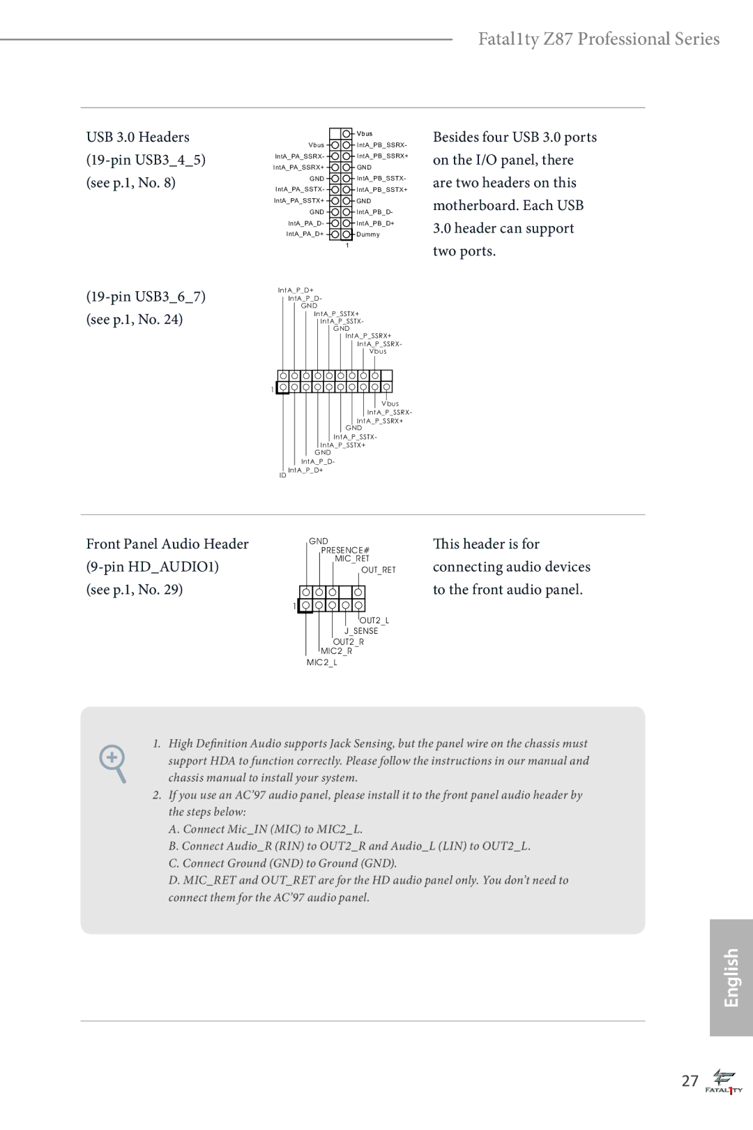
Fatal1ty Z87 Professional Series
English
Installing the CPU Fan and Heatsink
Dual Channel Memory Configuration
Installing Memory Modules Dimm
English
PCIe slots
Expansion Slots PCI and PCI Express Slots
See p.1, No
Jumpers Setup
Default
CLRCMOS1
BIOSSEL1
Bios Selection Jumper
System Panel Header Pin PANEL1 See p.1, No
Onboard Headers and Connectors
USB 2.0 Headers Pin USB45 See p.1, No Pin USB67
Power LED Header Pin PLED1 See p.1, No
Header can support two ports
Front Panel Audio Header Pin HDAUDIO1 See p.1, No
USB 3.0 Headers Pin USB345 See p.1, No
Header with a cable
Spdif Out Connector Please connect Pin SPDIFOUT1
Chassis Speaker Header
Pin SPEAKER1 Speaker to this header See p.1, No
This COM1 header supports a serial port module
PWR1
Pwrbtn
Smart Switches
Rstbtn
Cmos
Dr. Debug
Invalid Password
Problem related to USB devices. Please try removing all
Try re-installing the VGA card. If the problem still exists
Try re-installing the keyboard and mouse
Lieferumfang
Einleitung
Prozessor
Technische Daten
Plattform
Stil
Steckplatz
Erweiterungs
Speicher
Rückblende
Anschluss
Betriebssystem
Funktion
Support-CD
Überwachung
Deutsch
Standard
Jumpereinstellung
Siehe S , Nr
BIOS-Auswahl-Jumper
Integrierte Stiftleisten und Anschlüsse
USB 2.0-Stiftleisten Polig, USB45 Siehe S , Nr Polig, USB67
Betrieb-LED-Stiftleiste Polig, PLED1 Siehe S , Nr
Frontblende
USB 3.0-Stiftleisten
Lüfter. Falls Sie einen
Polig, CPUFAN1 Einen 4-poligen CPU Siehe S , Nr
Kontakt 1 bis
Bitte verbinden Sie diese
SLI/XFIRE
Wenn zwei Grafikkarten
Kann der Benutzer das
Intelligente Schalter
Ermöglicht das schnelle
Contenu de l’emballage
Introduction
Processeur
Spécifications
Plateforme
Armure
Graphiques
Stockage
Réseau
Connectique
Sur
Caractéris
Tiques du
CD inclus
Français
Voir p.1, No
Configuration des cavaliers jumpers
Cavalier Clear Cmos
Par défaut Fonction Clear Cmos
Sélection du cavalier du
Bios
Pwrbtn bouton d’alimentation
Embases et connecteurs de la carte mère
Connecteurs Serial ATA3 SATA301
Peut prendre en charge
Embases USB
USB345 à 19 broches USB 3.0 sur le panneau Voir p.1, No
Dotée de deux embases
Voir p.1, No CHAFAN3 à 3 broches PWRFAN1 à 3 broches
CHAFAN2 à 3 broches
Connecteur
Embase pour module infrarouge
Réinitialisation permet aux
Boutons intelligents
Marche permet aux
Utilisateurs d’allumer le
Contenuto della confezione
Introduzione
Specifiche
Grafica
Connettore
Supporto
Che del Bios
Caratteristi
CD di
Italiano
Cmos CLRCMOS1
Impostazione jumper
Vedere pag , n
Jumper di selezione Bios
Dei pin. Annotare i pin
Header e connettori sulla scheda
Di collegare i cavi
Connettori Serial ATA3 SATA301
Vedere pag , n Anteriore
Header USB Oltre alle quattro porte USB345 a 19 pin
Sono due header. Ciascun
Header USB 3.0 può
Connettore di
Pin
Di alimentazione di un
Connettore alimentazione Collegare questo
Connettore al connettore
SLI/XFIREPWR1
Interruttori intuitivi
Contenido del paquete
Introducción
Conjunto de
Especificaciones
Chips Memoria
Expansión
Ranura de
Gráficos
Conectores
Panel trasero I/O
Almacena
Miento
Monitor del hardware
CD de soporte
Certificaciones
Español
Consulte la pág.1, N.º
Instalación de los puentes
Puente de borrado de
Predeterminado Borrado de Cmos
Consulte la pág.1, N.º Bios Principal
Predeterminado Bios de copia de seguridad
Puente de selección del
Cables
Conectores y cabezales incorporados
De cuáles son los pines
Antes de conectar los
SATA345 SATA323 SATA301 SATA3A1A2 SATA3A3A4
HDAUDIO1 de 9 pines
Cabezales USB
Consulte la pág.1, N.º Frontal
Contiene un conector de
CPUFAN1 de 4 pines
Conector de alimentación Esta placa base
ATX
Con un conector de
Conector de alimentación Conecte este conector
Este cabezal COM1 admite un módulo de puerto serie
Permite a los usuarios
Interruptores inteligentes
Alimentación permite a
Los usuarios encender y
Комплект поставки
Введение
Спецификация
Система
Гнезда
Расширения
Графическая
ЛВС
Диск с ПО
Особенности
Сертификация
Русский
Установка перемычек
См. стр
Р е м ы ч к а в ы б о р а
Колодка системной Подключите Панели
Колодки и разъемы, расположенные на материнской плате
SATA3A1A2 См. стр.1 SATA3A3A4
SATA323 См. стр SATA345
Аудиоустройств к
Колодки USB Кроме четырех портов 19-контактная
Порта
AUDIO1
100
ATX12V1
101
102
Электронные кнопки
Clrcbtn
103
Conteúdo da embalagem
104
Especificações
Áudio
105
Conector
106
107
108
Consultar p.1, N.º
Configuração dos jumpers
109
Predefinição Limpar Cmos
Jumper de selecção da
110
111
Terminais e conectores integrados
112
113
Conectores da ventoinha
114
Da CPU
Conector de alimentação
115
Alimentação permite
116
Alimentação permite aos
Utilizadores ligar/desligar
117
Ambalaj İçeriği
118
Özellikler
Ses
119
Genişletme Yuvası
Grafikler
Bağlayıcı
120
Arka Panel I/O
Depolama
Donanımİzleyici
Bios Özelliği
121
Destek CDsi
122
Varsayılan
Bağlantı Teli Kurulumu
123
CMOSu Temizle Bağlantı Teli
124
Bios Seçme Bağlama Teli
125
Ekli Bağlantılar ve Bağlayıcılar
Güç LED Bağlantısı 3-pin PLED1 bkz. sf.1, No
126
Pin USB367
127
Içindir
ATX Güç Bağlayıcısı Pin ATXPWR1 Bkz. sf.1, No
128
Disk güç bağlayıcısına
129
130
Akıllı Anahtar
131
포장 내용물
후면 USB 3.0 브래킷 1 개
132
EAX1.0 EAX5.0 지원
133
ASMedia ASM1061 지원 eSATA 커넥터 1 개가 NCQ, Ahci
134
PXE 지원
Hdmi 출력 포트 1 개 Hdmi 입력 포트 1 개 DisplayPort 1 개
135
136
137
점퍼 설정
Clear Cmos 점퍼
백업 Bios
Bios 선택 점퍼
138
139
온보드 헤더 및 커넥터
PANEL1
PLED1
140
USB 2.0 헤더 USB45 페이지, 22 번 항목 참조 9 핀 USB67
19 핀 USB367
141
USB 3.0 헤더
19 핀 USB345
142
143
144
스마트 스위치
背面 USB 3.0 ブラケット
145
HDMI-IN
146
CrystalVoice に対応
147
ポートと DisplayPort ポートに対応
SBX Pro Studio に対応
148
149
Bios 機能
FCC 、CE 、WHQL
150
(p.1、No 参照)
151
152
(p.1、No 参照)デフォルト バックアップ Bios (メイン BIOS)
153
オンボードのヘッダーとコネクター
USB 2.0 ヘッダーは、2 つ
154
SATA301 、 No ) (SATA323:
パネルの 4 つの USB
(19 ピン USB367) (p.1、No 参照)
155
USB 3.0 ヘッダー
(19 ピン USB345)
156
PWR1)
157
(CLRCBTN)
158
(PWRBTN)
(RSTBTN)
159
Fatal1ty Z87 Professional 系列
160
161
LED)
162
163
164
165
跳线设置
166
Bios 选择跳线
此主板集成有两个 BIOS,一个是主 Bios BIOSA,一个是备用 Bios Bios
Biosaled or Biosbled 来识别当前哪一个 Bios 启动。
167
板载接脚和接口
SATA323
168
USB 2.0 接脚 USB45
19 针 USB367
169
USB 3.0 接脚
19 针 USB345
170
ATX 12V 电源接口
171
(4 针 SLI/XFIRE
172
智能开关
173
電子信息產品污染控制標示
174
繁體中文
CPU
175
176
LAN
177
178
179
180
跳線設定
181
Bios 選擇跳線
備用 Bios
本主機板設有兩個板載 BIOS,分別是主 Bios Biosa 與備用 Bios Bios
182
板載排針及接頭
183
USB 3.0 排針
184
185
插入 Pin 1 及 Pin 5。
186
ATX 12V 電源接頭
Pin ATX12V1 Pin ATX 12V 電源
Cmos 值。
187
188
Isi Kemasan
Permainan
Spesifikasi
189
Perlengkapan
Slot Ekspansi
190
Grafis
Konektor
191
Panel I/O
Belakang
192
193
194
Konfigurasi Jumper
Lihat hal , No
Bios Cadangan
Jumper Pilihan Bios
195
196
Header dan Konektor Onboard
Kabel data Sata untuk
197
Konektor Serial ATA3 SATA301
SATA3 ini mendukung
Port
198
Masing header USB
Dapat mendukung dua
Konektor Kipas Chassis dan Daya CHAFAN1 4-pin lihat hal , No
199
Pin SLI/XFIRE Hard disk bila dua kartu
200
Xfire
Ini dengan konektor daya
Lihat hal.3, No Pengguna menghapus Nilai Cmos dengan cepat
Tombol Pintar
201
Memungkinkan
Contact Information