Copyright Notice
Disclaimer
English
Motherboard Layout
ATXPWR1
Off No Link Blinking Data Activity
Panel
LAN Port LED Indications
Activity/Link LED
Package Contents
Introduction
Specifications
Rear Panel I/O
Connector
Bios Feature
USB
Microsoft Windows 7 / 7 64-bit / VistaTM / VistaTM 64-bit
CPU/Chassis Fan Multi-Speed Control
Voltage Monitoring +12V, +5V, +3.3V, Vcore
Compliant
ASRock Instant Boot
English Unique Features
ASRock Extreme Tuning Utility Axtu
ASRock Instant Flash
ASRock XFast LAN
ASRock APP Charger
ASRock XFast USB
ASRock XFast RAM
ASRock OMG Online Management Guard
ASRock Crashless Bios
ASRock Easy RAID Installer
ASRock Internet Flash
ASRock Interactive Uefi
Installation
Pre-installation Precautions
CPU Installation
Installation of CPU Fan and Heatsink English
Installation of Memory Modules Dimm
Installing a Dimm
Installing an expansion card
Expansion Slots PCI and PCI Express Slots
Pcie Slots
Description
Jumpers Setup
Jumper
Clear Cmos Jumper
Onboard Headers and Connectors
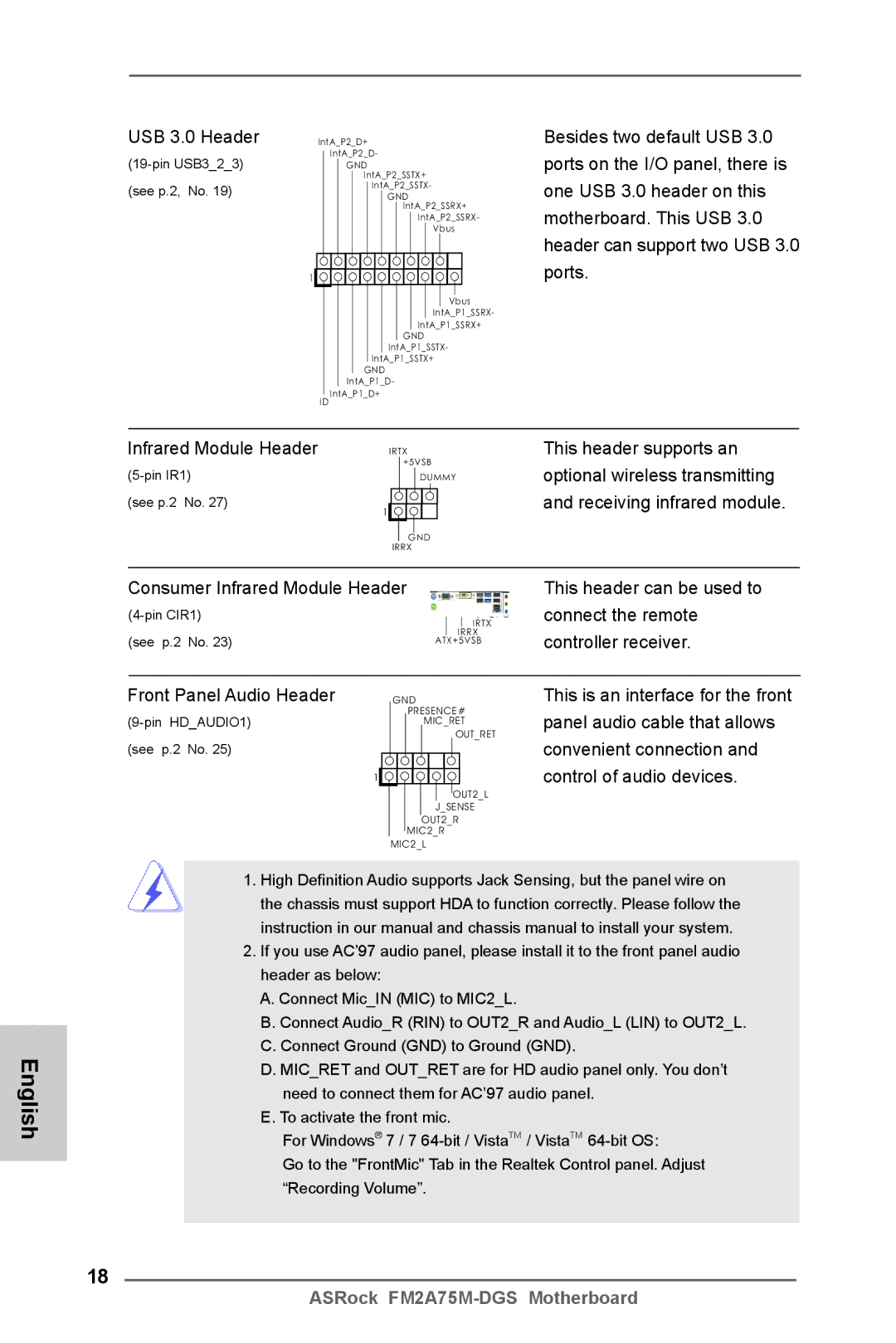
This header supports an
Optional wireless transmitting
USB 3.0 Header
Receiving infrared module
Functions
System Panel Header
Several system front panel
Chassis Speaker Header
Cable to the connector
Chassis and Power Fan Connectors
CPU Fan Connectors
Match the black wire to
Driver Installation Guide
\ RAID Installation Guide
English
Bios Information
Software Support CD information
Einführung
Kartoninhalt
Deutsch
Spezifikationen
Rückseite
Anschlüsse
An der
USB3.0
Zertifizierungen
Cmos löschen
Einstellung der Jumper
Jumper Einstellun Beschreibung
Nur gelöscht werden, wenn die CMOS-Batterie entfernt wird
Anschlüsse
AnschlussBeschreibung
Optionales, drahtloses Sende
USB 3.0-Header
Dieser Header unterstützt ein
Und Empfangs-Infrarotmodul
System Panel-Header
Mehrere Funktion der
Systemvorderseite
ATX-Netz-Header
Gehäuselautsprecher-Header Schließen Sie den
Diesen Header an
Verbinden Sie die ATX- Stromversorgung mit diesem Header
Stromversorgung an
ATX 12V Anschluss Bitte schließen Sie an diesen
Anschluss die ATX
COM-Anschluss-Header Dieser COM-Anschluss
BIOS-Information
Contenu du paquet
Français
Spécifications Français
Panneau arrière
Connecteurs
CD d’assistance
Surveillance
Système
Réglage des cavaliers
Le cavalier Description
Effacer la Cmos
En-têtes et Connecteurs sur Carte
Connecteurs Série ATA3
En-tête USB
Transfert et de réception sans
Cet en-tête supporte un module
Infrarouge optionnel de
Fil
En-tête du panneau système Cet en-tête permet d’utiliser
Plusieurs fonctions du
Panneau système frontal
Connecteur du ventilateur
En-tête du haut-parleur Veuillez connecter le De châssis
Cet en-tête
De l’UC
12V sur ce connecteur
Connecteur ATX Veuillez connecter une unité
’alimentation électrique ATX
En-tête de port COM Cette en-tête de port COM est
Informations sur le Bios Informations sur le CD de support
Italiano
Contenuto della confezione
Memoria
Specifiche
Piattaforma
Slot di
Connettori
Pannello
Posteriore
CD di
Compatibi
Lità SO Certificazioni
Setup dei Jumpers
Resettare la Cmos
Jumper Settaggio del Jumper
Cavi dati Serial ATA Sata
Collettori e Connettori su Scheda
Connettori Serial ATA3
Collettore USB
Per la trasmissione e la
Questo collettore supporta
Moduli ad infrarossi optional
Ricezione senza fili
Collettore casse telaio Collegare le casse del telaio a
Collettore pannello di sistema
Diverse funzioni di sistema
Questo collettore
Combaciare il filo nero al pin
Connettore ventolina CPU
CPU a questo connettore e far
Terra
Collettore porta COM Questo collettore porta COM è
Connettore ATX 12 Collegare un alimentatore ATX
A questo connettore
Utilizzato per supportare il
Informazioni sul Bios Software di supporto e informazioni su
Introducción
Contenido de la caja
Español
Español Especificación
Trasero
Entrada/Salida
De Panel
Conectores
CD de soport
Monitor Hardware
Certificaciones
Setup de Jumpers
Jumper Setting
Limpiar Cmos
Cabezales y Conectores en Placas
Este cabezal soporta un
Wireless opcional
Cabezal USB
Módulo infrarrojos de
Cabezal de panel de sistema
Sistema
Cabezal de alimentación ATX Conecte la fuente de
Conector a una toma de
Conector de ATX 12V power Tenga en cuenta que es
Necesario conectar este
Corriente con el enchufe ATX
Bios Información Información de Software Support CD
Введение
Русский
Комплектность
Спецификации
Плате
USB
Колодки и
Компактдиск
Операцион
Ные системы
Сертификаты
Установка перемычек
Перемычка Установка Описание
Колодки и разъемы на плате
Колодка USB
Данная колодка позволяет
Pled индикатор питания системы
Reset кнопка сброса
Pwrbtn кнопка питания
Hdled индикатор активности жесткого диска
Контакты 1-3 подключены
Колодка питания 12V-ATX Обратите внимание, что к этому
Информация о Bios
Giriş
Paket İçindekiler
Türkçe
Özellikler
Konektör
Bios Özelliği
Arka Panel
Destek CD’si
Sertifikalar
Jumperların Ayarı
Jumper Ayar
CMOS’u temizleme
Yerleşik Fişler ve Konektörler
Aktarma ve alma kızılötesi
USB 3.0 Fişleri
Bu fiş, isteğe bağlı bir kablosuz
Modülünü destekler
Kasa Hoparlörü Fişi
Sistem Paneli Fişi
Işlevini barındırır
Bağlayın
Fanına bu konektöre bağlayın
CPU Fan Konektörü
Lütfen fan kablolarını CPU
Bağlayın
Bios Bilgileri Yazılım Destek CD’si bilgileri
제품소개
시리얼 ATA Sata 데이터 케이블 2 개 선택 사양 차폐 1 개
소켓 FM2 100W 프로세서 지원
AMD 의 Cool ‘n ’ Quiet TM 기술 지원
SATA3
CPU/ 섀시 저소음 팬
마이크로 소프트 Windows 7/7 64 비트 /Vista TM
CPU/ 섀시 팬 멀티스피드 컨트롤
전압 감시 기능 +12V,+5V,+3.3V,Vcore
Vista TM 64 비트 와 호환
개의 기본 USB 2.0 포트
시리얼 ATA3 커넥터
시리얼 Atasata 데이터 케이블
습니다 . 각각의 USB 2.0 헤더
USB 3.0 포트 이외에도 마더보
USB 3.0 헤더
패널에 있는 2 개의 기본적
드에 1 개의 USB 3.0 헤더가 있
것입니다
시스템 콘넥터 콘넥터는 시스템 전면 패
널기능을 지원하기 위한
새시 스피커 헤더
CPU 팬 케이블을 이 커넥터에
프린트 포트 헤더
케이블을 팬 커넥터에 연결하 고 접지 핀에는 검은색 전선을 연결하십시오 CPU 팬 커넥터
맞추십시오
연결해야 충분한 전력을
ATX 12V 파워 콘넥터 ATX 12V 플러그가 달린
전원공급장치를 이 커넥터에
공급할 수 있습니다 . 그러지
Micro ATX フォームファクター 8.9-in x 7.6-in, 22.6 cm x 19.3 cm
I/O パネルシールド
Socket FM2 100W Processors に対応
Micro ATX フォームファクター
X 7.6-in, 22.6 cm x 19.3 cm
AMD 社 Cool ‘n’ QuietTM をサポート
100
101
CPU/ シャーシ / 電源ファンタコメータ CPU/ シャーシ静音ファン CPU/ シャーシファンマルチ速度制御
ジャンパ設定
102
オンボードのヘッダとコネクタ類
103
104
USB 3.0 ヘッダ
105
シャーシに付いている電源スイッチ、リセットスイッチ、システムステータ
106
プリントポートヘッダ
107
108
このマザーボードは Microsoft Windows 7 / 7 64-bit / VistaTM / VistaTM
主板簡介
109
110
111
112
清除 Cmos
Serial ATA Sata
113
Serial ATA3 接口
USB 2.0 擴展接頭
114
USB 3.0 擴展接頭
115
板功能。
ATX 電源接頭
116
CPU 風扇接頭
ATX 12V 接頭
117
本主板支持各種微軟視窗操作系統:Microsoft Windows 7/7 64 位元 /VistaTM
電子信息產品污染控制標示
118
119
Micro ATX 規格 8.9 英吋 x 7.6 英吋 , 22.6 公分 x 19.3 公分
120
121
122
USB 2.0 擴充接頭
123
SATA3 接口。
USB 2.0 接口之外,這款
124
USB 3.0 擴充接頭
125
重啟鍵等各種連線。
126
ATX 電源接頭
ATX 12V 電源接口
支援光碟訊息
127
128
Penjelasan
Isi Paket
Bahasa Indonesia
Spesifikasi
129
Papan Belakang
Ciri-ciri Bios
130
Penghubung
Kontrol Multi-Kecepatan Kipas CPU/casis
131
Kipas diam CPU/casis
Sertifikasi
Installing OS on a HDD Larger Than 2TB in Ahci Mode
132
133
Drv4E CtrlB5 Langeng
Key in dh Drv number, for example key in dh 4E
134
Choose Usable Physical Drive List to select Raid HDD
135
136
Windows VistaTM 64-bit
137
138
Windows 7 64-bit
Finish