2.3 CPU Installation |
|
|
|
|
|
|
|
|
|
|
|
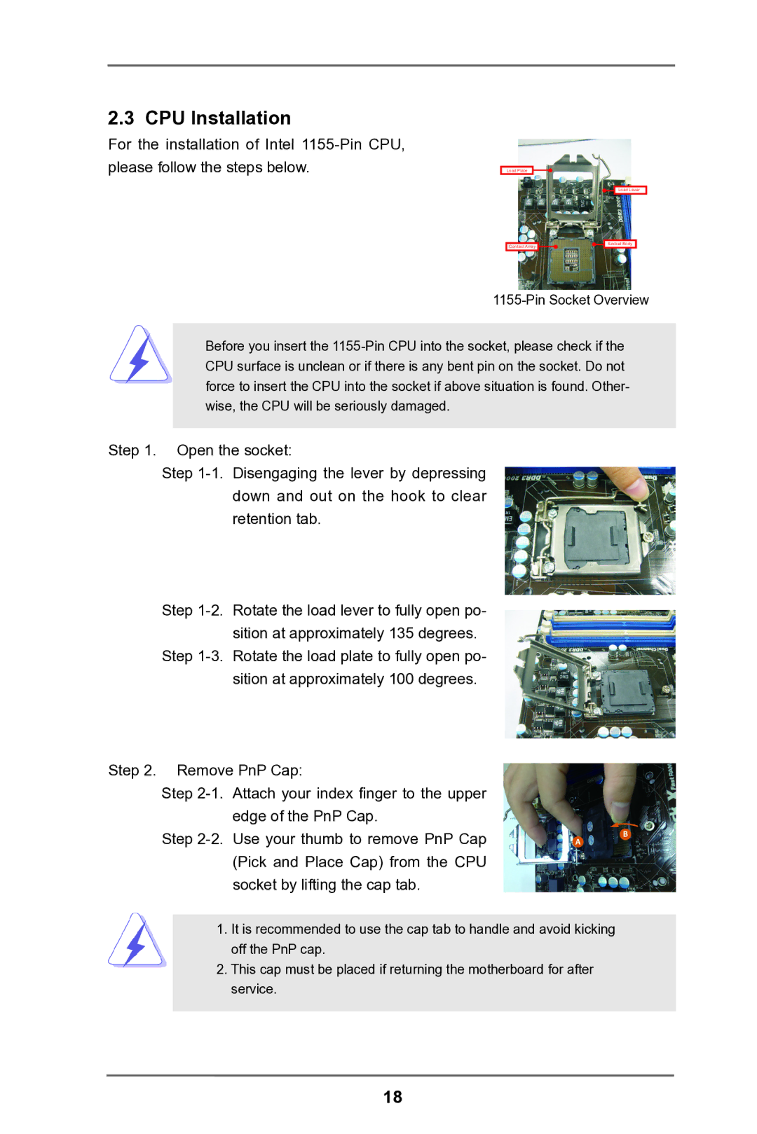
For the installation of Intel |
|
|
|
|
|
|
|
|
|
|
|
please follow the steps below. |
|
|
|
|
|
|
|
|
|
|
|
|
| Load Plate |
|
|
|
|
|
|
|
| |
|
|
|
|
| |||||||
|
|
|
|
|
|
|
|
|
| ||
|
|
|
|
|
|
|
|
|
|
|
|
|
|
|
|
|
|
|
|
| Load Lever |
| |
|
|
|
|
|
|
|
|
|
|
|
|
|
|
|
|
|
|
|
| Socket Body |
|
| |
|
|
| Contact Array |
|
|
|
|
|
|
| |
|
|
|
|
|
|
|
|
|
|
|
|
| |||||||||||
Before you insert the
Step 1. Open the socket:
Step
Step | Rotate the load lever to fully open po- |
| sition at approximately 135 degrees. |
Step | Rotate the load plate to fully open po- |
| sition at approximately 100 degrees. |
Step 2. Remove PnP Cap: | |
Step | Attach your index finger to the upper |
| edge of the PnP Cap. |
Step | Use your thumb to remove PnP Cap |
| (Pick and Place Cap) from the CPU |
| socket by lifting the cap tab. |
A
B
1.It is recommended to use the cap tab to handle and avoid kicking off the PnP cap.
2.This cap must be placed if returning the motherboard for after service.
18
