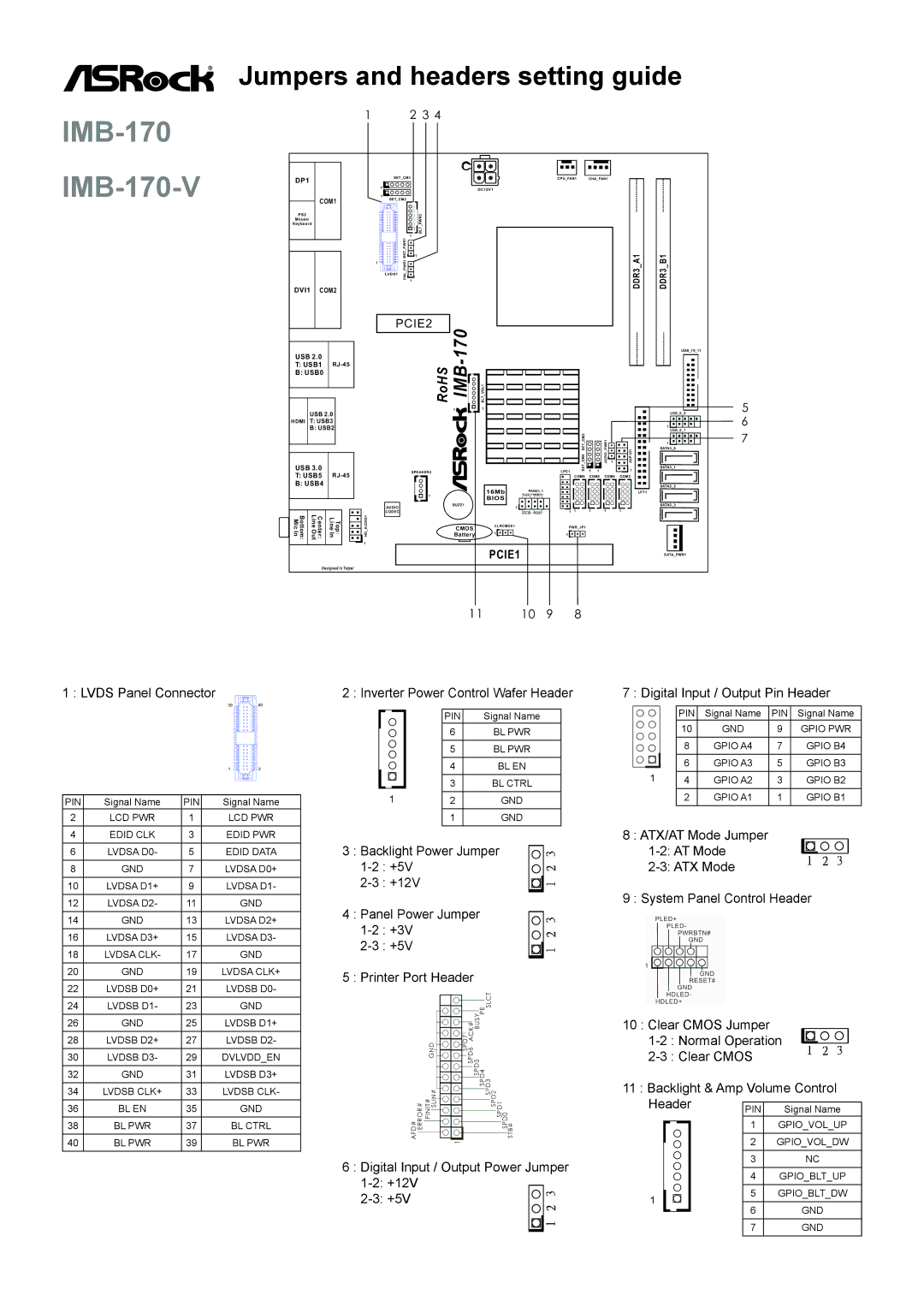
Jumpers and headers setting guide

IMB-170 IMB-170-V


1

2 3 4


DP1


SET_CM1


CPU_FAN1

CHA_FAN1


1


DC12V1


1


COM1


SET_CM2


PS2


PWR3


PS2


Mouse/


Keyboard


Keyboard


_


BLT


1


PWR1


1


DDR3 A1

DDR3 B1


1


LVDS1


1


DVI1

COM2


BKTPNLPWR1


PCIE2

170


USB_10_11


USB 2.0


-


T: USB1

RJ-45


RoHS

IMB


B: USB0


BLT VOL1


5


1


USB 2.0


USB_8_9


6

HDMI

T: USB3


1


B: USB2


USB_6_7


CM4 SET CM3


JGPIO PWR1


1

7


JGPIO1

SATA3_0


1


USB 3.0


SET


1

SATA3_1


SPEAKER2


LPC1

1

1


T: USB5

RJ-45


COM6

COM5

COM4

COM3


B: USB4


SATA2_2


16Mb

PANEL 1


LPT1


1


PLED PWRBTN


BIOS


AUDIO

BUZZ1


1


SATA2_3


1

1


1


1


Mi Bottom: cIn

LineOu t


CODEC


HDLED RESET


1


Center:

LineIn Top:

HD AUDIO1


CMOS

CLRCMOS1


PWR_JP1


Battery

1


1


1


PCIE1


SATA_PWR1


Designed in Taipei


11

10

9


8


1 : LVDS Panel Connector


2 : Inverter Power Control Wafer Header

7 : Digital Input / Output Pin Header


39

40


PIN


Signal Name


PIN

Signal Name


PIN

Signal Name


10

GND


9

GPIO PWR


6


BL PWR


8


GPIO A4


7

GPIO B4


5


BL PWR


6


GPIO A3


5

GPIO B3


1

2


4


BL EN


1


3


BL CTRL


4


GPIO A2


3

GPIO B2


1


2


GPIO A1


1

GPIO B1


2


GND


PIN

Signal Name

PIN


Signal Name


2

LCD PWR

1


LCD PWR


1


GND


4

EDID CLK

3


EDID PWR


8 : ATX/AT Mode Jumper


6

LVDSA D0-

5


EDID DATA

3 : Backlight Power Jumper

1-2: AT Mode


1-2 : +5V


2-3: ATX Mode


8

GND

7


LVDSA D0+


2-3 : +12V


10

LVDSA D1+

9


LVDSA D1-


9 : System Panel Control Header

12

LVDSA D2-

11


GND

4 : Panel Power Jumper


14

GND

13


LVDSA D2+


1-2 : +3V


16

LVDSA D3+

15


LVDSA D3-


2-3 : +5V


18

LVDSA CLK-

17


GND


20

GND

19


LVDSA CLK+

5 : Printer Port Header


22

LVDSB D0+

21


LVDSB D0-


24

LVDSB D1-

23


GND


10 : Clear CMOS Jumper


26

GND

25


LVDSB D1+


28

LVDSB D2+

27


LVDSB D2-


1-2 : Normal Operation


30

LVDSB D3-

29


DVLVDD_EN


2-3 : Clear CMOS


32

GND

31


LVDSB D3+


11 : Backlight & Amp Volume Control


34

LVDSB CLK+

33


LVDSB CLK-


Header


36

BL EN

35


GND


PIN


Signal Name

38

BL PWR

37


BL CTRL


1


GPIO_VOL_UP


40

BL PWR

39


BL PWR


2


GPIO_VOL_DW


6 : Digital Input / Output Power Jumper


3


NC


4


GPIO_BLT_UP


1-2: +12V


5


GPIO_BLT_DW


2-3: +5V


1


6


GND


7


GND


Page 1
Image 1
ASRock manual IMB-170 IMB-170-V, Imb

IMB-170-V specifications

The ASRock IMB-170-V is a compact and feature-rich industrial motherboard designed for a variety of applications demanding reliability and performance. Ideal for embedded solutions, digital signage, thin clients, and automation, this motherboard integrates advanced technologies to maximize functionality while ensuring durability.

One of the standout features of the IMB-170-V is its support for Intel’s 6th and 7th generation Core processors, commonly known as Skylake and Kaby Lake. This compatibility allows users to harness the processing power of these CPUs while benefiting from energy efficiency and lower heat generation. The board supports a maximum of 32GB DDR4 RAM via two SO-DIMM slots, offering ample memory bandwidth for multitasking and resource-intensive applications.

The IMB-170-V incorporates a wide range of connectivity options, including multiple USB 3.0 and USB 2.0 ports, allowing for fast data transfer and the connection of various devices. Furthermore, it features a Mini PCIe slot, which facilitates the addition of wireless communication modules, such as Wi-Fi and Bluetooth, enhancing connectivity for IoT applications.

In terms of video output, the motherboard supports dual displays via HDMI and VGA ports, accommodating diverse display needs in various environments. This dual-display capability is crucial for applications such as digital signage, where multiple screens often display information concurrently.

Another essential aspect of the ASRock IMB-170-V is its built-in hardware monitoring capabilities, which ensure system stability and longevity. The board features temperature sensors and fan control, which are essential in industrial settings where thermal management is critical to maintaining operational efficiency.

The IMB-170-V also emphasizes reliability with its industrial-grade components that meet stringent quality tests. This makes it suitable for use in challenging environments that demand robust performance without failure.

In addition, the motherboard’s compact size makes it an excellent choice for space-constrained applications. It can be easily integrated into various chassis, aiding in the development of compact systems tailored to specific industrial applications.

In summary, the ASRock IMB-170-V is engineered to meet the demands of modern industrial computing. With its support for powerful processors, extensive memory options, versatile connectivity, dual display capabilities, and robust design, it positions itself as an exceptional choice for developers and integrators in the industrial sector.