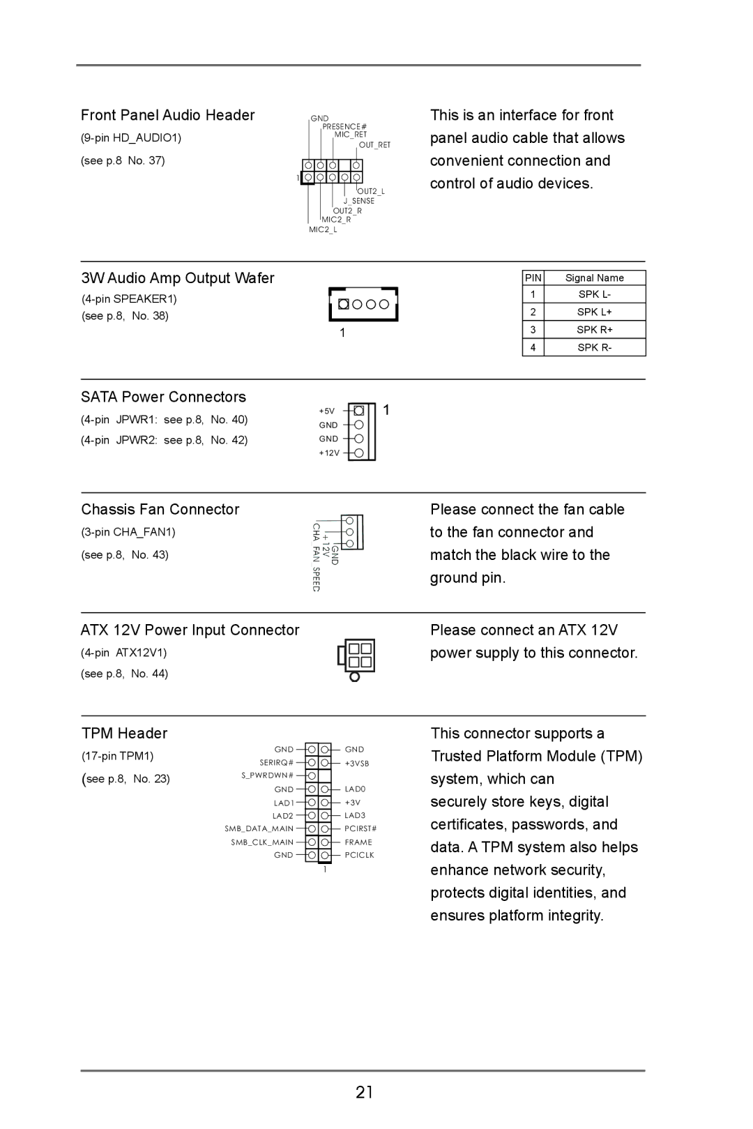
Front Panel Audio Header |
|
| GND | ||||||||
|
|
|
| PRESENCE# | |||||||
|
|
|
|
| MIC_RET | ||||||
|
|
|
|
|
|
|
|
|
| OUT_RET | |
(see p.8 No. 37) | 1 |
|
|
|
|
|
|
|
|
|
|
|
|
|
|
|
|
|
|
|
| ||
|
|
|
|
|
|
|
|
|
|
| |
|
|
|
|
|
|
|
|
|
| OUT2_L | |
|
|
|
|
|
|
| J_SENSE | ||||
|
|
|
|
|
| OUT2_R | |||||
|
|
|
|
| MIC2_R | ||||||
|
|
| MIC2_L | ||||||||
This is an interface for front panel audio cable that allows convenient connection and control of audio devices.
3W Audio Amp Output Wafer
(see p.8, No. 38)
1
PIN | Signal Name |
1 | SPK L- |
2 | SPK L+ |
3 | SPK R+ |
4 | SPK R- |
SATA Power Connectors
JPWR1: see p.8, | No. 40) | +5V | ||
GND | ||||
JPWR2: see p.8, | No. 42) | |||
GND | ||||
|
|
| +12V |
1
Chassis Fan Connector | Please connect the fan cable |
to the fan connector and | |
(see p.8, No. 43) | match the black wire to the |
| ground pin. |
|
|
ATX 12V Power Input Connector | Please connect an ATX 12V |
power supply to this connector. | |
(see p.8, No. 44) |
|
TPM Header
This connector supports a
GND | ||
SERIRQ# | ||
(see p.8, No. 23) | ||
S_PWRDWN# | ||
| GND | |
| LAD1 | |
| LAD2 | |
| SMB_DATA_MAIN | |
| SMB_CLK_MAIN | |
| GND |
![]() GND
GND
![]() +3VSB
+3VSB
LAD0
+3V
LAD3
PCIRST#
FRAME
PCICLK
1
Trusted Platform Module (TPM) system, which can
securely store keys, digital certificates, passwords, and data. A TPM system also helps enhance network security, protects digital identities, and ensures platform integrity.
21
