F. Enter Windows system. Click the icon on the lower right hand taskbar to enter Realtek HD Audio Manager. Click “Audio I/O”,
select “Connector Settings” | , choose “Disable front |
panel jack detection”, and save the change by clicking “OK”.
System Panel Header
(see p.10 No. 13)
1
PLED+
PLED-
PWRBTN#
GND
DUMMY RESET#
GND HDLED-
HDLED+
This header accommodates several system front panel functions.
Chassis Speaker Header |
|
1 |
(see p.10 No. 15)
SPEAKER DUMMY
DUMMY +5V
Please connect the chassis speaker to this header.
Chassis Fan Connector
GND
(see p.10 No. 16)+12V
CHA_FAN_SPEED
Please connect a chassis fan cable to this connector and match the black wire to the ground pin.
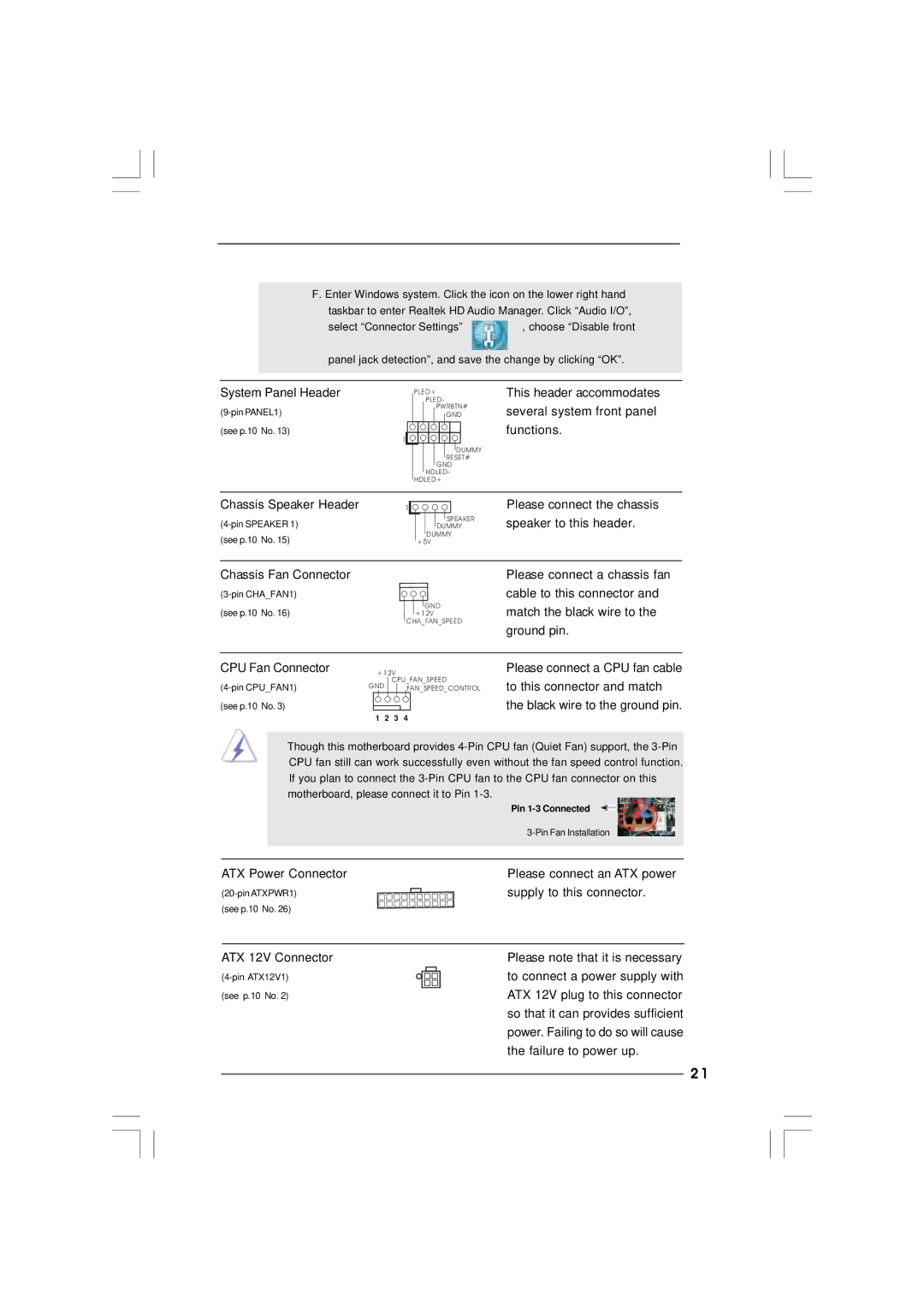
CPU Fan Connector
+12V
CPU_FAN_SPEED
GND | FAN_SPEED_CONTROL |
(see p.10 No. 3)
1 2 3 4
Please connect a CPU fan cable to this connector and match the black wire to the ground pin.
Though this motherboard provides
| Pin |
| |
ATX Power Connector | Please connect an ATX power |
supply to this connector. | |
(see p.10 No. 26) |
|
ATX 12V Connector
(see p.10 No. 2)
Please note that it is necessary to connect a power supply with ATX 12V plug to this connector so that it can provides sufficient power. Failing to do so will cause the failure to power up.
2 1