Power LED Header | 1 |
|
|
|
| Please connect the chassis | |
|
|
|
| ||||
|
|
|
|
| PLED+ | power LED to this header | |
|
|
|
|
| PLED- |
| |
(see p.11, No. 21) |
|
| PLED+ | to indicate the system’s | |||
|
| ||||||
|
|
|
|
| |||
|
|
|
|
|
| power status. | |
|
|
|
|
|
|
| |
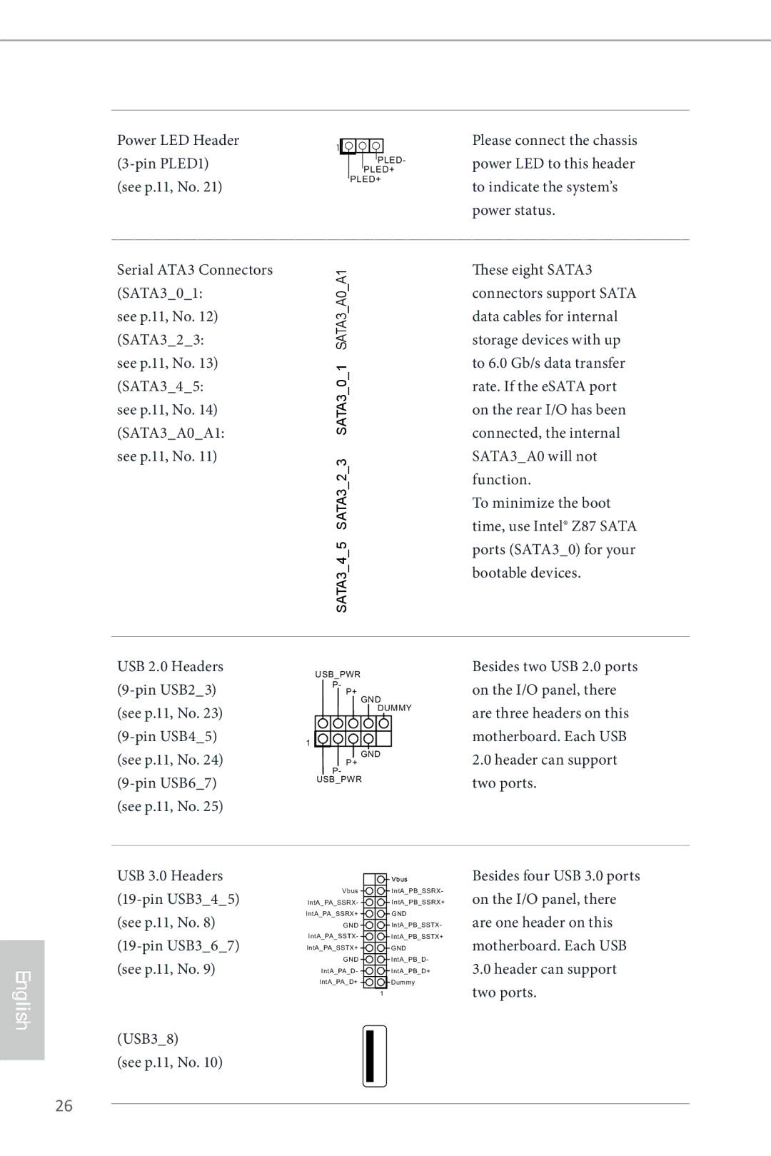
Serial ATA3 Connectors | A1 | These eight SATA3 | |||||
(SATA3_0_1: | connectors support SATA | ||||||
A0 | |||||||
see p.11, No. 12) | SATA3 | data cables for internal | |||||
(SATA3_2_3: | storage devices with up | ||||||
see p.11, No. 13) | 1 |
|
|
| to 6.0 Gb/s data transfer | ||
(SATA3_4_5: | 0_ |
|
|
| rate. If the eSATA port | ||
see p.11, No. 14) | SATA3 | on the rear I/O has been | |||||
|
|
|
|
| |||
(SATA3_A0_A1: |
|
|
|
|
| connected, the internal | |
see p.11, No. 11) | 3 |
|
|
| SATA3_A0 will not | ||
| 2_ |
|
|
| function. | ||
| SATA3 | To minimize the boot | |||||
|
|
|
|
|
| ||
|
|
|
|
|
| time, use Intel® Z87 SATA | |
| 5 |
|
|
| ports (SATA3_0) for your | ||
| 4 |
|
|
| bootable devices. | ||
| SATA3 | ||||||
|
| ||||||
USB 2.0 Headers
(9-pin USB2_3)
(see p.11, No. 23)
(9-pin USB4_5)
(see p.11, No. 24)
(9-pin USB6_7)
(see p.11, No. 25)
USB_PWR
P- P+ GND DUMMY
1
GND
Besides two USB 2.0 ports on the I/O panel, there are three headers on this motherboard. Each USB
2.0header can support two ports.
English
USB 3.0 Headers
(19-pin USB3_4_5)
(see p.11, No. 8)
(19-pin USB3_6_7)
(see p.11, No. 9)
(USB3_8)
(see p.11, No. 10)
Vbus
IntA_PA_SSRX- IntA_PA_SSRX+
GND
IntA_PA_SSTX-
IntA_PA_SSTX+
GND
IntA_PA_D-
IntA_PA_D+
Vbus
IntA_PB_SSRX- IntA_PB_SSRX+
GND
IntA_PB_SSTX- IntA_PB_SSTX+
GND
IntA_PB_D-
IntA_PB_D+
Dummy
1
Besides four USB 3.0 ports on the I/O panel, there are one header on this motherboard. Each USB
3.0header can support two ports.
26