Infringe
Copyright Notice
Page
Z87 OC Formula/ac
Motherboard Layout
Z87 OC Formula
English
English
I/O Panel
Speed LED Status Description
Off No Link Blinking Data Activity
Introduction
Package Contents
Platform
Specifications
Style
Formula
Memory
Chipset
Expansion
Slot
Rear Panel
Audio
Connector
Feature
Storage
Hardware
Support
Certifica
FCC, CE, Whql
ASRock Formula Drive
Unique Features
ASRock Uefi System Browser
ASRock Easy Driver Installer
ASRock Good Night LED
WiFi + BT Module
Installing the SMA Wi-Fi Antenna Cables
Fasten the screw nuts to secure the connec- tors
Installation
Installing the CPU
English
English
Installing the CPU Fan and Heatsink
Dual Channel Memory Configuration
Installing Memory Modules Dimm
English
Expansion Slots PCI and PCI Express Slots
MINIPCIE1 mini-PCIe slot is used for WiFi module
Pcie slots
Mini-PCIe slots
Default
Jumpers Setup
CLRCMOS1
See p.1 or 2, No
Pwrbtn Power Switch
Onboard Headers and Connectors
Power LED Header Pin PLED1 See p.12, No
See p.1 or 2, No SATA123 See p.1 or 2, No SATA345
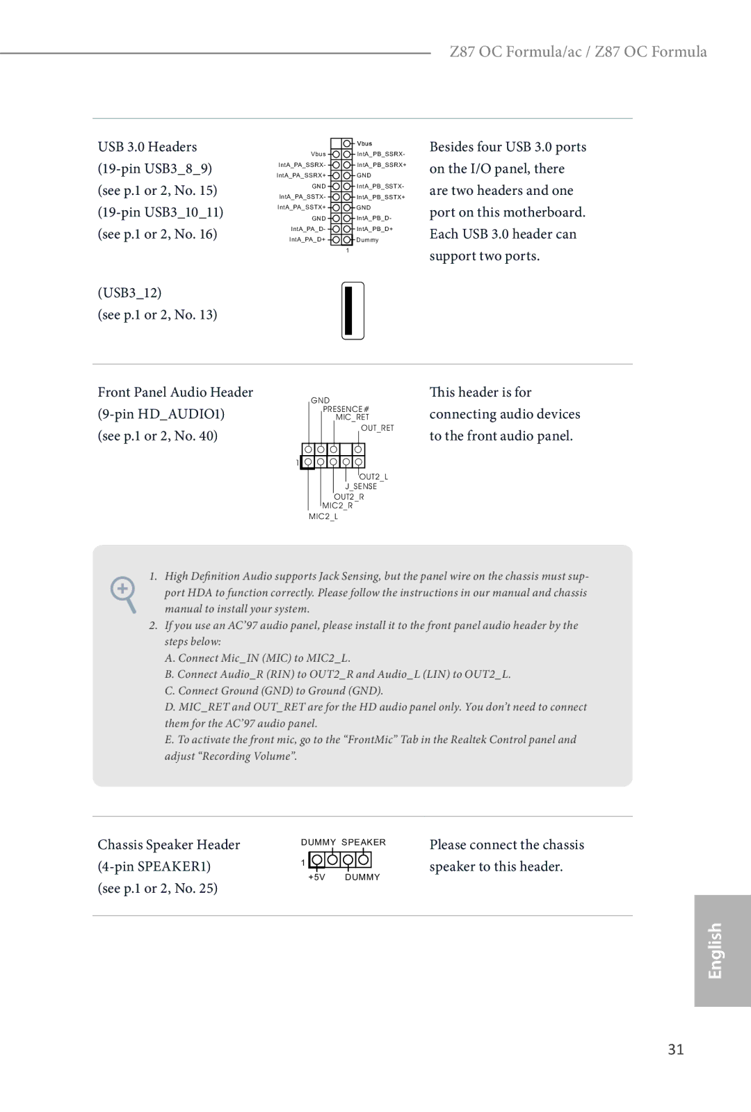
Header can support two ports
USB 3.0 Headers
USB312 See p.1 or 2, No
Chassis Speaker Header 4-pin SPEAKER1 see p.1 or 2, No
Pin MOSFAN1
ATX Power Connector Pin ATXPWR1 See p.1 or 2, No
This COM1 header supports a serial port module
PWR1
CON2
5VPCH
05PCH
Smart Switches
Pwrbtn
Rstbtn
See p.1 or 2 No
LN2 Mode Switch LN2MODE1 See p.1 or 2, No
Lieferumfang
Einleitung
Plattform Stil OC Formula Kit Prozessor
Technische Daten
Speicher
Chipsatz
Erweiter
Ungssteck
Rückblende
Anschluss
Support-CD
Betriebssystem
Zertifizierungen
CMOS-löschen-Jumper
Jumpereinstellung
Standard Cmos löschen
Siehe S oder 2, Nr
Pwrbtn Ein-/Austaste
Integrierte Stiftleisten und Anschlüsse
Betrieb-LED-Stiftleiste Polig, PLED1 Siehe S , Nr
Ihre bootfähigen Geräte
Siege S oder 2, Nr SATA123 Siehe S oder 2, Nr SATA345
USB 2.0-Stiftleisten
USB312 Siehe S oder 2, Nr
USB 3.0-Stiftleisten
Audiostiftleiste
Frontblende
ATX-Netzanschluss Polig, ATXPWR1 Siehe S oder 2, Nr
Polig, SLI/XFIRE Anschluss mit einem
Installiert sind
PCH-1,5-V-IREF
CON1
Clrcbtn
Intelligente Schalter
Bios
SEL1
LN2MODE1
Contenu de l’emballage
Spécifications
Plateforme
Kit OC
Fente
Mémoire
’expansion
Graphiques
Connectique
Réseau
Du panneau
Arrière
Stockage
Ahci et « Hot Plug »
Connecteurs SATA3 6,0 Go/s ASMedia ASM1061
Surveillance
CD inclus
Système
’exploitation Certifications
Cavalier Clear Cmos
Configuration des cavaliers jumpers
Par défaut Fonction Clear Cmos
Voir p.1 ou 2, No
Pwrbtn bouton d’alimentation
Embases et connecteurs de la carte mère
Voir p.12, No
Embase LED d’alimentation PLED1 à 3 broches
Connecteurs Serial ATA3 SATA301
SATA123 Voir p.1 ou 2, No SATA345
Embase du haut-parleur du
USB312 Voir p.1 ou 2, No
Châssis
SPEAKER1 à 4 broches
Français
MOSFAN1 3 broches
Broches
Connecteur d’alimentation ATX
Voir p.1 ou 2, No Cartes graphiques sont
Cette embase COM1 prend en charge un module de port série
VOLCON2
VOLCON1
MINUS1
Boutons intelligents
PLUS1
MENU1
PCIE2 PCIE4 PCIE6
Interrupteur mode LN2 LN2MODE1 Voir p.1 ou 2, No
Contenuto della confezione
Introduzione
Specifiche
Piattaforma
Stile superiore Kit OC Formula
Slot di
Memoria
Espansione
PCIE5
Posteriore
Pannello
Archiviazione
Del Bios
Connettore
Caratteristiche
CD di
Supporto
Certificazioni
Impostazione jumper
Cmos
Vedere pag o 2, n
Header sul pannello del sistema
Header e connettori sulla scheda
Porte Sata Intel Z87 SATA30 per i dispositivi
Questi dieci connettori SATA3 supportano cavi
Di’avvio
Oltre alle due porte USB Sul pannello I/O, su
Può supportare due porte
USB312 Vedere pag o 2, n
Header altoparlante
Chassis Dello chassis a questo
MOSFAN1 a 3 pin
Connettore alimentazione Collegare questo
Connettore di alimentazione ATX da 12
SLI/XFIRE
Madre
CPU
Comp
Interruttori intuitivi
Interruttore modalità LN2 LN2MODE1 Vedere pag o 2, n
Contenido del paquete
Introducción
Especificaciones
Plataforma
Kit de OC
Chips Memoria
Conjunto de
Ranura de
Expansión
Panel trasero
Características
Conectores
CD de soporte
Monitor del
Certificaciones
Puente de borrado de
Instalación de los puentes
Cmos CLRCMOS1
Predeterminado Borrado de Cmos
Conectores y cabezales incorporados
Cabezal del panel del Sistema
PANEL1 de 9 pines
Para dispositivos de
Consulte la pág.1 ó
SATA123
Consulte la pág ó
Cabezal de altavoces del
Chasis
SPEAKER1 de 4 pines
CPUFAN2 de 3 pines
Conectores del ventilador De la CPU CPUFAN1 de 4 pines
Conector de alimentación
ATX
SLI/XFIREPWR1 de
Con un conector de
Pines Cuando haya dos tarjetas Consulte la pág ó
Placa base
VOLCON2 de 7 pines Ring
Probe TM VOLCON1 de 7 pines
Voltaje PCH1,5V Iref
Voltaje 2.º Comp CPU
Interruptores inteligentes
Permite a los usuarios resetear
Interruptor de alimentación El interruptor de alimentación
Permite a los usuarios
Sistema desde el Bios a o el
BIOSBIOSSEL1
Bios B
Interruptor del Modo Si el Modo Lento está activado
Комплект поставки
Введение
Спецификация
Платформа
Комплект OC Formula
Память
Чипсет
Гнезда
Расширения
100
Запоминающие
101
Устройства
Разъемы
Диск с ПО
102
Контроль
Сертификация
103
Установка перемычек
Колодки и разъемы, расположенные на материнской плате
104
Колодка системной Панели Контактная, PANEL1 См. стр или 2
105
AUDIO1
106
107
108
Xfire
XFIREPWR1
Pchiref Напряжение PCH1,5V
109
Iref
5VPCH Напряжение PCH 1,5V 05PCH
110
Электронные кнопки
Переключатель Питания
Использованием Bios a или
Переключатель Если включен медленный Медленного режима
Режим работы, процессор
112
Conteúdo da embalagem
Especificações
113
Estilo a
Memória
114
Ranhuras de
Expansão
Áudio
115
Do painel
Traseiro
116
Armazenamento
Conector
CD de suporte
117
Sistema
Operativo
118
Configuração dos jumpers
Jumper para limpar o
Predefinição Limpar Cmos
119
Terminais e conectores integrados
120
USB312 Consultar p.1 ou 2, N.º
121
Terminal do altifalante do
Chassis
MOS
122
Conector de alimentação
ATXPWR1 de 24 pinos Consultar p.1 ou 2, N.º
123
Placa principal
Este terminal COM1 suporta um módulo de porta de série
PCH1,5V
124
Cmos Clrcbtn
125
Ou Bios B
Arranque a partir do Bios a
126
Interruptor de modo Se o Modo lento estiver
127
Ambalaj İçeriği
Özellikler
128
Stili OC Formula Kiti
129
130
Ses
Arka Panel I/O
131
Bios Özelliği
Depolama
Bağlayıcı
Destek CDsi
132
Donanım
Belgeler
133
Bağlantı Teli Kurulumu
CMOSu Temizle Bağlantı Teli
Varsayılan CMOSu Temizle
Ekli Bağlantılar ve Bağlayıcılar
134
Bkz. s.1 veya 2, No
135
USB 3.0 Bağlantıları
136
USB312 Bkz. s.1 veya s.2, No
Kasa Hoparlör Bağlantısı
137
Kasa, Güç ve MOS Fan Bağlayıcıları
ATX Güç Bağlayıcısı Pin ATXPWR1 Bkz. s.1 veya s.2, No
Pinli SLI/XFIRE Takılıyken lütfen bu
138
Bağlayıcıyı sabit disk güç
Bu COM1 bağlantısı seri bağlantı yuvası modülünü destekler
139
140
Akıllı Anahtar
Yavaş Mod Yavaş Mod açıksa, işlemci en
141
Önyüklenmesini sağlar
Ortadan kaldırmaya yardımcı
142
포장 내용물
HDD/SSD 랙 탑재 전면 USB 3.0 패널 1 개 HDD 나사 4 개
후면 USB 3.0 브래킷 1 개 OC 지지대 10 개
143
DDR3 Dimm 슬롯 4 개
144
Intel Extreme Memory Profile XMP1.3/1.2 지원
Hdmi 기술 지원 최대 해상도 4K × 2K 4096x2304 @ 24Hz
145
146
147
148
점퍼 설정
Clear Cmos 점퍼
기본값 Clear Cmos
온보드 헤더 및 커넥터
149
PANEL1 또는 2 페이지 , 27 번 참조
PLED1 12 페이지 , 17 번 참조
150
USB 3.0 헤더 19- 핀 USB389 또는 2 페이지 , 15 번
151
USB312 또는 2 페이지 , 13 번 참조
HDAUDIO1 또는 2 페이지 , 40 번 참조
CPUFAN1
152
CPUFAN2
24 핀 ATXPWR1 또는 2 페이지 , 12 번
153
SLI/XFIREPWR1
COM1
154
155
스마트 스위치
+ / Rapid OC 버튼
MINUS11 또는
Bios a 또는 Bios B 에서
BIOSSEL1
156
SLOWMODE1
157
I/O パネルシールド
前面 USB 3.0 パネル、2.5 HDD/SSD ラック付き HDD 用ねじ
OC Formula 電源キット
158
OC Formula コネクタキット
OC Formula 冷却キット
DDR3 Dimm スロット
159
4400/4600 Pixel Shader 5.0, DirectX
(4096x2304)@24Hz
160
161
電圧監視:+12V 、+5V 、+3.3V 、CPU Vcore
162
ステータス Oled
FCC 、CE 、WHQL
35)
163
27)
164
(9 ピン USB45)
165
Intel Z87 Sata ポート
パネルの 2 つの USB
166
167
ATX12V 電源コネクター (8 ピン ATX12V1)
168
(8 ピン ATX12V3)
(4 ピン SLI/XFIRE
169
CON1、
5VPCH PCH 1.5V 電圧 05PCH
(PWRBTN)
170
(RSTBTN)
(CLRCBTN)
BIOSSEL1 ( 1 ページ ムを Bios a または Bios B か
(SWITCH1 )(1 ペー PCIE2
171
PCIe ON/OFF スイッチ PCIE1
感谢您购买 ASRock Z87 OC Formula/ac / Z87 OC Formula 主板,这是按照
172
Style OC Formula
173
174
175
176
177
178
跳线设置
PANEL1
179
PLED1
180
SATA301 最高 6.0 Gb/s 数据传输
Sata 数据线。
181
USB 3.0 接脚 (19 针 USB389)
HDAUDIO1
182
(8 针 ATX12V3)
183
184
+/- 快速 OC 按钮
185
(MINUS1 :参见第
OC 频率。
186
PCIE1 PCIE2 PCIE4 PCIE6 PCIe ON/OFF 开关可让您启
18 个)
187
電子信息產品污染控制標示
感謝您購買 ASRock Z87 OC Formula/ac / Z87 OC Formula 主機板,本主機板經
188
OC Formula 電源組件
189
OC Formula 接頭組件
OC Formula 冷卻組件
190
LED)
191
Bios 功能
192
PCIe 開啟/關閉開關 Post 狀態檢查 PSC
Start8 、MeshCentral 、Splashtop Streamer
193
電壓監控: +12V 、+5V 、+3.3V 、CPU Vcore
相容 Microsoft Windows 8 / 8 64 位元 / 7 / 7 64 位元
194
跳線設定
Pin PANEL1
195
196
USB 3.0 排針 Pin USB389
197
Pin USB31011
Pin HDAUDIO1
198
Pin ATX12V3
199
ATX 12V 電源接頭。若
Pin 5。 SLI/XFIRE 電源接頭
200
5VPCH:
05PCH:
+ / 快速 OC 開關
201
MINUS1 :請參閱第
PLUS1 :請參閱第 1 頁
Bios a 或 Bios B 開機。
Bios 選擇開關 Bios
202
LN2 模式開關
203
Isi Kemasan
Spesifikasi
204
Style Kit OC Formula
Memori
205
Slot Ekspansi
Grafis
206
Panel I/O
Belakang
207
Fitur Bios
Penyimpanan
Konektor
Dukungan CD
208
Perangkat
Keras
Lihat hal atau 2, No Default
Konfigurasi Jumper
209
Header dan Konektor Onboard
210
Lihat hal atau 2, No
211
USB312 Lihat hal atau 2, No
212
Header Speaker Chassis
Sambungkan speaker
CHAFAN3 3-pin
213
CHAFAN4 3-pin
PWRFAN1 3-pin Lihat hal atau 2, No MOSFAN1 3-pin
Header COM1 ini mendukung modul port seri
214
215
PCH 1,5V
PCH 1,05V
216
Tombol Pintar
217
OFFSWITCH1
Page
Page
Page
Contact Information
EC-Declaration of Conformity