Manuals
/
ASRock
/
Computer Equipment
/
Personal Computer
ASRock
Z87 OC Formula
manual
Installing the CPU Fan and Heatsink
Models:
Z87 OC Formula
1
30
121
121
Download
121 pages
51.89 Kb
27
28
29
30
31
32
33
34
Specification
Install
Connection Diagram
RTC Alarm Power On
Password
CPU Integrated VR Faults
RAS# to CAS# Delay tRCD
Timing Configurator
Accessing Data Playing Video
Jumpers Setup
Page 30
Image 30
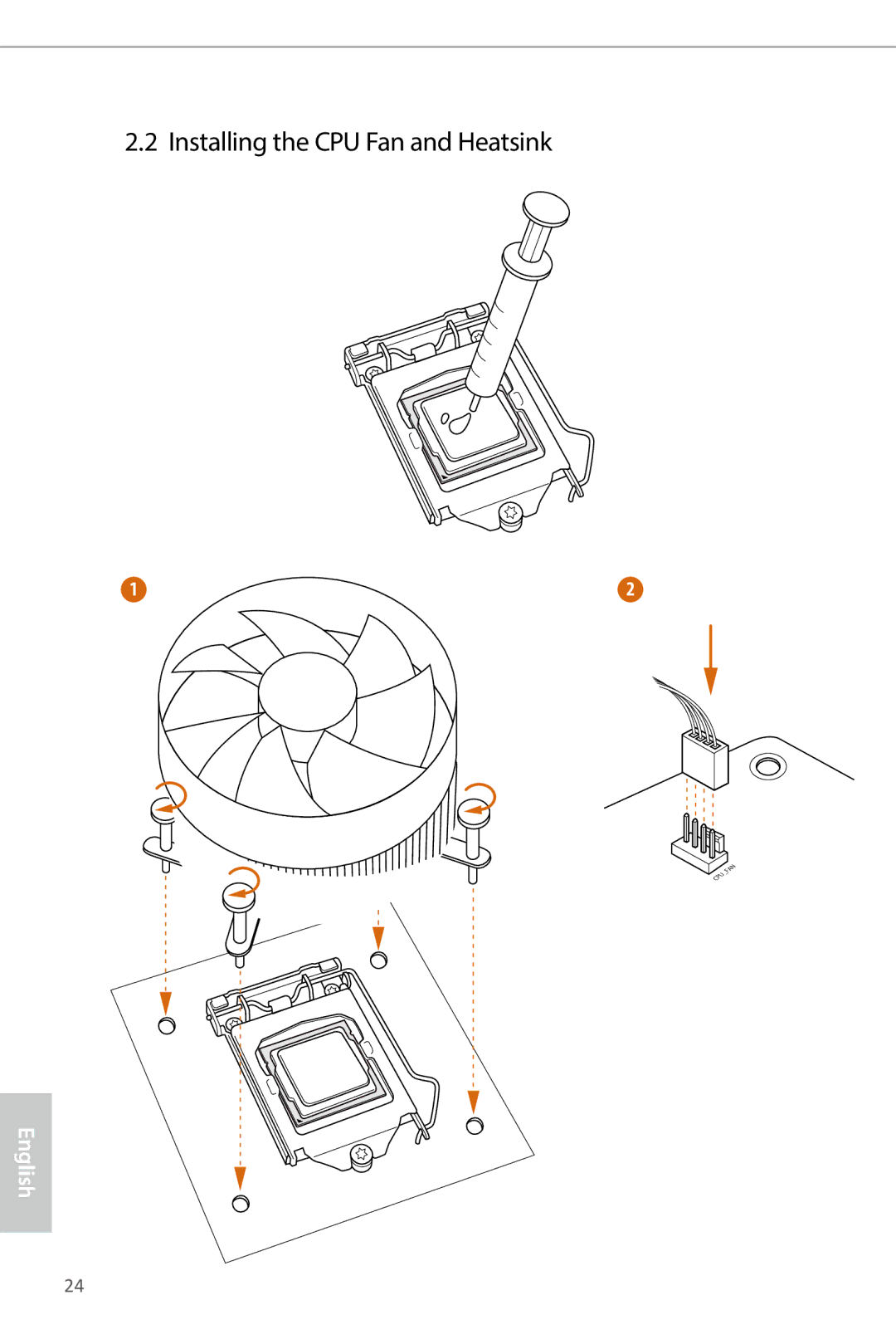
2.2 Installing the CPU Fan and Heatsink
1
2
English
24
Page 29
Page 31
Page 30
Image 30
Page 29
Page 31
Contents
Page
Copyright Notice
Disclaimer
DTS, Inc., All Rights Reserved
Contents
Software and Utilities Operation
Page
Package Contents
Introduction
Specifications
Platform
Chipset
LAN
Z87 OC Formula/ac / Z87 OC Formula
Certifica
Unique Features
ASRock XFast RAM
ASRock Crashless Bios
ASRock Easy RAID Installer
ASRock OMG Online Management Guard
Fine-Tuning V-Controller
ASRock Easy Driver Installer
ASRock Fast Boot
Timing Configurator
ASRock USB Key
ASRock FAN-Tastic Tuning
ASRock Good Night LED
ASRock Conformal Coating
Motherboard Layout
Z87 OC Formula/ac
Z87 OC Formula
No. Description
English
I/O Panel
Activity / Link LED Status Description
WiFi + BT Module
Installing the SMA Wi-Fi Antenna Cables
Fasten the screw nuts to secure the connec- tors
Installation
Installing the CPU
English
English
Installing the CPU Fan and Heatsink
Installing Memory Modules Dimm
Dual Channel Memory Configuration
English
Pcie Slot Configurations
Expansion Slots PCI and PCI Express Slots
Jumpers Setup
CLRCMOS1
Onboard Headers and Connectors
Pwrbtn Power Switch
Power LED Header Pin PLED1 See p.12, No
USB 3.0 Headers
ATX Power Connector Pin ATXPWR1 See p.11 or 12, No
PWR1
Pchiref
Smart Switches
Pwrbtn
See p.11 or 12 No
Status Oled
Before Entering Windows
Under Windows
Debug Codes
Code Description
Problem related to USB devices. Please try removing all
Front USB 3.0 Panel Installation Guide
Front USB 3.0 Panel with
Rear USB 3.0 Bracket Installation Guide
Using the HDMI-In Port
Connection Diagram
Double-click the Formula Drive
Installing Two SLITM-Ready Graphics Cards
Slitm and Quad Slitm Operation Guide
ASRock Flexible SLI Bridge Connector Cable
Driver Installation and Setup
For Slitm and Quad Slitm mode
Installing Two CrossFireXTM-Ready Graphics Cards
CrossFire Bridge
Installing Three CrossFireXTM-Ready Graphics Cards
Installing Four CrossFireXTM-Ready Graphics Cards
Double-click the AMD Catalyst Control
Drivers Menu
Installing Drivers
Running The Support CD
Utilities Menu
Operation Mode
Installing Formula Drive
Using Formula Drive
Formula Drive
Tools
XFast RAM
OC Tweaker
System Info
Tech Service
Intel Rapid Start Technology
System Requirements
Setup Guide
Configuring Rapid Start
Double-click the Intel Rapid Start Technology Manager icon
Using Rapid Start
English
Intel Smart Connect Technology
Installing ASRock Smart Connect Utility
Click Apply to enable Smart Connect
Using Smart Connect
English
Configuring and Using MeshCentral
Intel Remote Wake Technology
Creating a Mesh
Downloading and Installing Mesh Agent
Click Install / Update
Waking up Your PC using PC
Waking up Your PC Using Mobile Device
Configuring and Using Splashtop
Setup Guide
Using Remote Wakeup
Using Remote Control
Accessing Data Playing Video
Start8
Installing Start8
Configuring Start8
Style
Configure
Control
Desktop
About
Introduction
Uefi Menu Bar
Navigation Keys
END
Main Screen
Active Page on Entry
Uefi Guide
User OC Profile
Load Optimized CPU OC Setting
OC Tweaker Screen
OC Tweaking
Advanced Turbo
Load Optimized GPU OC Setting
CPU Configuration CPU Ratio
CPU Cache Ratio
GT Voltage Mode
Long Duration Power Limit
Short Duration Power Limit
Filter PLL Frequency
GT Voltage Offset
Dram Timing Configuration Load XMP Setting
Dram Configuration Dram Tweaker
Dram Reference Clock
Write Recovery Time tWR
RAS# to CAS# Delay tRCD
Command Rate CR
RAS to RAS Delay tRRD
TREFI
Four Activate Window tFAW
CAS Write Latency tCWL
TCKE
TRDWR
Command Tri State
MRC Fast Boot
TRDWRDR
Fivr Switch Frequency Offset
Dimm Exit Mode
Fivr Configuration Fivr Switch Frequency Signature
CPU Integrated VR Faults
CPU Voltage Mode
PWM Phase Control
Dram Switching Frequency
PWM Current Threshold
CPU Cache Voltage Offset
CPU Cache Override Voltage
CPU Cache Adaptive Voltage
System Agent Voltage Offset
Advanced Screen
CPU Configuration
No-Execute Memory Protection
Package C State Support
CPU Thermal Throttling
Intel Virtualization Technology
Chipset Configuration
Render Standby
Restore on AC/Power Loss
Igpu Multi-Monitor
Onboard HD Audio
Sata Aggressive Link Power Management
Storage Configuration
Sata Mode Selection
Sata Controllers
ASMedia SATA3 Mode
Sata Boot ROM
Hard Disk S.M.A.R.T
Intel Rapid Start Technology
Intel Smart Connect Technology
Super IO Configuration
Serial Port1
Serial Port1 Address
Acpi Configuration
USB Keyboard/Remote Power On
Ring-In Power On
RTC Alarm Power On
USB Mouse Power On
USB Controller
USB Configuration
Intel USB 3.0 Mode
Legacy USB Support
Tools
Internet Setting
Secure Backup Uefi
Network Configuration
Instant Flash
Dehumidifier Period
Dehumidifier CPU Fan Setting
Dehumidifier Function
Dehumidifier Duration
Hardware Health Event Monitoring Screen
MOS Fan 1 Setting
Over Temperature Protection
Boot From Onboard LAN
Boot Screen
Fast Boot
Setup Prompt Timeout
Full Screen Logo
Boot Failure Guard
Boot Failure Guard Count
AddOn ROM Display
Launch PXE OpROM Policy
Launch Storage OpROM Policy
Launch Video OpROM Policy
Secure Boot
Supervisor Password
User Password
Security Screen
Exit Screen
Contact Information
Top
Page
Image
Contents