3.HARDWARE SETUP
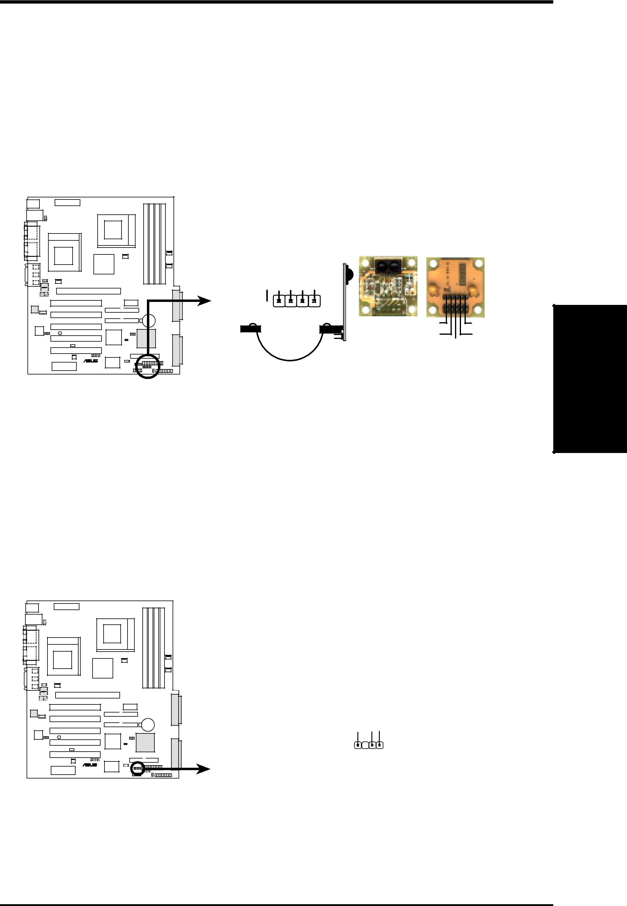
9)Standard Infrared Module ConnectorThis connector supports an optional wireless transmitting and receiving infrared module. This module mounts to a small opening on system cases that support this feature. You must also configure the setting through UART2 Use Infrared (see 4.4.2 I/O Device Configuration) to select whether UART2 is directed for use with COM2 or IrDA. Use the five pins as shown in Back View and connect a ribbon cable from the module to the motherboard SIR connector according to the pin definitions.
Front View Back View
|
| IR |
|
+5V | (NC) IRRX | GND IRTX |
1 
IRTX +5V
GND (NC)
IRRX
This lead is for a chassis designed for chassis intrusion detection. This requires an external detection mechanism such as a chassis intrusion monitor/sensor or microswitch. When any chassis component is removed, the sensor is triggered and a
Stand By) | ChassisSignal Ground |
+5Volt (PowerSupply | |
| |
1 |
|
CHASSIS
Connectors
3. H/W SETUP
ASUS | 39 |