
P5SD2-X SE specifications
The Asus P5SD2-X SE is a versatile motherboard designed for users seeking a balance between performance and affordability. As part of the ASUS family, it brings a wealth of features that cater to both everyday computing and more demanding tasks.One of the standout features of the P5SD2-X SE is its support for Intel’s LGA 775 socket, which allows for a range of compatible processors from the Pentium 4 to the dual-core series. This flexibility makes it an excellent choice for users looking to upgrade components without needing an entirely new system. Additionally, the motherboard supports DDR2 memory, with a maximum capacity of 4GB, further enhancing its overall performance for multitasking and demanding applications.
In terms of expansion capabilities, the P5SD2-X SE is equipped with PCI Express x16 slots, accommodating a variety of modern graphics cards. This is particularly beneficial for gamers or users who require advanced graphics processing. Furthermore, it features multiple PCI slots for additional cards such as sound and network adapters, ensuring robust customization options tailored to the user’s needs.
The motherboard also incorporates various storage technologies, supporting SATA II hard drives with RAID configurations. This functionality not only enhances data transfer speeds but also provides redundancy options for data protection, critical for users who manage large amounts of data. It also includes support for IDE devices, catering to legacy components that may still be in use.
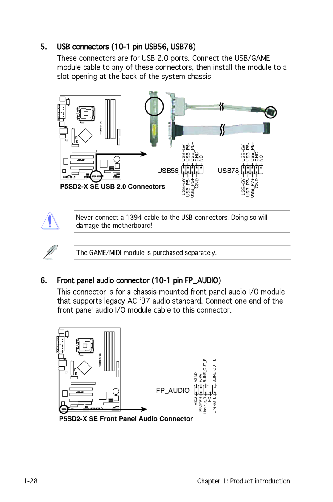
Connectivity is another highlight of the Asus P5SD2-X SE. It offers several USB 2.0 ports, facilitating easy connections to peripherals such as printers, mice, and keyboards. The integrated audio capabilities provide a decent surround sound experience, eliminating the need for separate sound cards for most users.
For system stability and efficiency, ASUS has equipped the P5SD2-X SE with various proprietary technologies, such as their AI Overclocking and Q-Fan technologies. These features help maximize performance while ensuring that the system remains cool and quiet during operation.
In summary, the Asus P5SD2-X SE is a solid choice for users who seek reliable performance in a budget-friendly package. Its comprehensive feature set, including support for modern processors, ample expansion options, and various connectivity choices, makes it an excellent foundation for both casual and more demanding computing tasks.