Motherboard
Offer to Provide Source Code of Certain Software
Copyright 2012 ASUSTeK Computer INC. All Rights Reserved
Contents
Software support
Appendices
Electrical safety
Safety information
Operation safety
About this guide
Conventions used in this guide
Where to find more information
Typography
Bold text
P8H61-M2/TPM/SI R2.0 specifications summary
USB
E7361P8H61-M2-TPM-SI R2.0Manua10 16/12 14344 PM
Welcome
Package contents
Special features
Intel H61 Express Chipset
Gigabit LAN solution
PCI Express
Intel Smart Response Technology SSD Speed with HDD Capacity
Network iControl
Innovative Asus features
AI Suite
Asus Anti-Surge Protection
GPU Boost
Asus CrashFree Bios
Asus Fan Xpert
Asus MyLogo2
Before you proceed
Standby Power LED
Screw holes
Placement direction
Motherboard overview
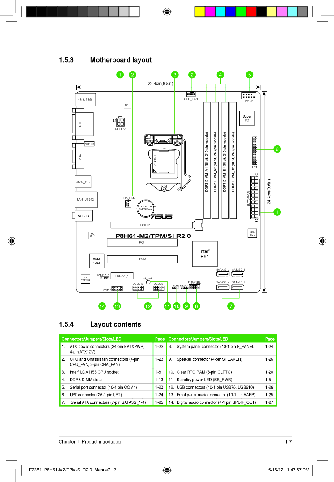
Motherboard layout
Layout contents
To install a CPU Locate the CPU socket on the motherboard
Installing the CPU
Central Processing Unit CPU
Load lever Retention tab
PnP cap CPU notches
Load plate
Gold
Mark
Insert the load lever under the retention tab
Installing the CPU heatsink and fan
P8H61-M2/TPM/SI R2.0 CPU fan connector
Uninstalling the CPU heatsink and fan
Overview
System memory
Dimm
Memory configurations
DDR3-2200 O.C. MHz capability
DDR3-2250 O.C. MHz capability
DDR3-2133 O.C. MHz capability
DDR3-2000 O.C. MHz capability
DDR3-1333 MHz capability Sandy Bridge CPU
DDR3-1600 O.C. MHz capability
DDR3-1333 MHz capability IVY Bridge CPU
DDR3-1066 MHz capability IVY Bridge CPU
Following table shows how to use the Dimm slots
DDR3-1066 MHz capability Sandy Bridge CPU
Sides SS Single-sided DS Double-sided Dimm support
Removing a Dimm
Installing a Dimm
To remove a Dimm
Outward to unlock the Dimm
Expansion slots
Clear RTC RAM 3-pin Clrtc
Jumpers
Audio 2, 4, 6, or 8-channel configuration
Connectors
Rear panel ports
LAN port LED indications
ATX power connectors 24-pin EATXPWR, 4-pin ATX12V
Internal connectors
Serial port connectors 10-1 pin COM1
CPU and Chassis fan connectors 4-pin CPUFAN, 3-pin Chafan
This connector supports several chassis-mounted functions
LPT connector 26-1 pin LPT
Reset button 2-pin Reset
Hard disk drive activity LED 2-pin +HDLED
Configuration Sata Mode Selection
Serial ATA 3.0 Gb/s connectors 7-pin SATA3G1-4
Front panel audio connector 10-1 pin Aafp
480Mbps connection speed
USB 2.0 connectors 10-1 pin USB78, USB910
Speaker connector 4- pin Speaker
P8H61-M2/TPM/SI R2.0 Digital audio connector
Digital audio connector 4-1 pin Spdifout
Click an item to install
Installing an operating system
Software support
Support DVD information
Asus Update utility
Managing and updating your Bios
Installing Asus Update
Updating the Bios
Asus EZ Flash
Select Update Bios from file, then click Next
Recovering the Bios
Asus CrashFree Bios 3 utility
Booting the system in DOS environment
Asus Bios Updater
Before updating Bios
Bios Updater screen appears as below
Updating the Bios file
Bios menu screen
Bios setup program
Entering Bios Setup at startup
Entering Bios Setup after Post
EZ Mode
Menu bar on top of the screen has the following main items
Advanced Mode
Menu bar
Menu items
Configuration fields
Back button
Submenu items
System Language English
Main menu
System Date Day xx/xx/xxxx
System Time
User Password
Administrator Password
Ai Tweaker menu
Asus MultiCore Enhancement Enabled
Memory Frequency Auto
GPU Boost
Disabled Disables this function
CPU Power Management
Dram Timing Control
Decrease average heat production
TPM Support Disabled
CPU Configuration
Intel Adaptive Thermal Monitor Enabled
Advanced menu
Execute Disable Bit Enabled
Limit Cpuid Maximum Disabled
Intel Virtualization Technology Disabled
Hardware Prefetcher Enabled
IntelR Smart Connect Technology Isct Configuration Disabled
PCH Configuration
High Precision Timer Enabled
System Agent Configuration
Sata Configuration
Onboard Devices Configuration
USB Configuration
8 APM
Network Stack
Monitor menu
CPU Temperature / MB Temperature xxxºC/xxxºF
CPU / Chassis Fan Speed xxxx RPM or Ignore / N/A
CPU Voltage, 3.3V Voltage, 5V Voltage, 12V Voltage
Chassis Q-Fan Control Enabled
CPU Q-Fan Control Enabled
CPU temperature
Silent
Chassis Upper Temperature 70ºC
Anti Surge Support Enabled
Chassis Lower Temperature 40ºC
Chassis Fan Max. Duty Cycle% 100%
Bootup NumLock State On
Boot menu
Full Screen Logo Enabled
Wait for ‘F1’ If Error Enabled
Setup Mode EZ Mode
Option ROM Messages Force Bios
UEFI/Legacy Boot Enabled both Uefi and Legacy
Boot Option Priorities
Asus EZ Flash 2 Utility
Tools menu
Asus SPD Information
Asus O.C. Profile
Exit menu
E7361P8H61-M2-TPM-SI R2.0Manua28
IC Canadian Compliance Statement
Federal Communications Commission Statement
Canadian Department of Communications Statement
Asus Recycling/Takeback Services
Telephone
Address
Online support
Support fax
Declaration of Conformity