Telephone installation
1.Attach the mounting bracket.
If the mounting bracket is not already attached, slide the tabs into the holes as shown. Snap the mounting bracket onto the base.
Telephone installation
If there are two
Telephone installation
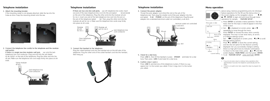
4.Connect the power adapter.
Thread the power adapter cord behind the slot at the back of the telephone base. Then plug the smaller end of the power adapter into the jack labeled 9V AC POWER on the back of the telephone. Plug the power adapter into a standard electrical outlet not controlled by a wall switch.
Menu operation
Feature setup, memory programming and a few individual feature operations for the 993 use the menus shown in the screen display. Use the navigation buttons (![]() ,
, ![]() ,
, ![]() ,
, ![]() , ENTER) to begin, end and move through menu operations (for example, FEATURE SETUP).
, ENTER) to begin, end and move through menu operations (for example, FEATURE SETUP).
modular wall jack for Line 2. Make sure the telephone line cords snap firmly into place at both ends.
Modular | Modular wall |
|
wall jack | jack for Line 2 | Black telephone line |
for Line 1 |
| |
| cord | |
|
|
POWER jack
Electrical outlet not controlled ![]() by a wall switch.
by a wall switch.
Power adapter
Menu topic or data
FEATURE SETUP
ONE TOUCH
1. | Press ENTER to activate a menu operation. The first |
| menu item for this topic or data will appear in line four |
| of the screen. |
2. | When is displayed on screen, press or |
| repeatedly to move through the menu. |
3. | Press ENTER to choose the menu item currently |
Clear telephone |
Menu item
Menu scroll indicator
displayed. This may be a lower level menu, an action, | |
or a feature settings screen. | |
4. When | is displayed on screen, press or to scroll |
line cord |
Menu
through setting options. |
2. Connect the telephone line cord(s) to the telephone and the modular |
wall jack(s). |
If there is a single |
telephone line cord |
L1 or L1/L2 on the back of the telephone. Plug the other end into the |
3.Connect the handset to the telephone.
Plug the coiled handset cord into the handset jack on the left side of the telephone. Plug the other end of the coiled handset cord into the handset, then hang up.
slot
5. Check for a dial tone. |
Press LINE 1, then lift the handset or press SPEAKER and listen for a dial |
PHONE SETTINGS
![]() LINE 1
LINE 1
PRIMARY LINE
Feature
Current Setting
5. | Press or ENTER to store the current setting |
| and show the next option for the feature currently |
| displayed. When you successfully change a setting, |
| there is a high pitch tone to indicate confirmation. |
6. | To return to the main menu, press or until the |
| screen displays MAIN MENU and then press ENTER. |
7. | To exit FEATURE SETUP, press and hold ENTER. |
wall jack. Make sure the telephone line cord snaps firmly into place at both |
ends. |
Black telephone line
![]() cord
cord
tone. Then press LINE 2 and listen for a dial tone. |
6. Confirm Lines 1 and 2. |
Press LINE 1 and dial one of the telephone numbers. If there is a busy |
signal, line 1 is the number you called. If line 2 rings, line 2 is the number |
you called. |
![]() NOTES:
NOTES:
1.If you do not press a key to continue menu operations within approximately 30 seconds, the telephone automatically exits the menu.
2.If there is a low pitch (error) tone, repeat the steps to program the feature.