Appendix
LEDs
The
Power LED: | Lights when the CPU Switch is running. |
Ready LED: | Lights when the connected PC or CPU Switch is running. |
Port Select LED: | Lights to indicate the currently selected port. |
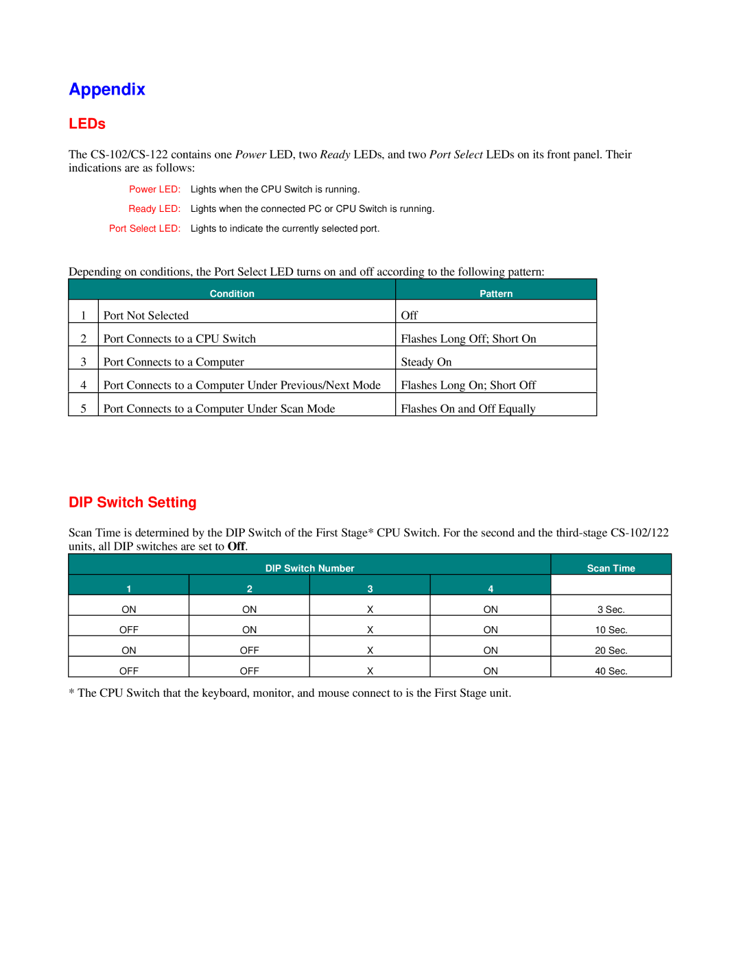
Depending on conditions, the Port Select LED turns on and off according to the following pattern:
| Condition | Pattern |
1 | Port Not Selected | Off |
2 | Port Connects to a CPU Switch | Flashes Long Off; Short On |
3 | Port Connects to a Computer | Steady On |
4 | Port Connects to a Computer Under Previous/Next Mode | Flashes Long On; Short Off |
5 | Port Connects to a Computer Under Scan Mode | Flashes On and Off Equally |
DIP Switch Setting
Scan Time is determined by the DIP Switch of the First Stage* CPU Switch. For the second and the
|
| DIP Switch Number |
| Scan Time | |
1 | 2 |
| 3 | 4 |
|
ON | ON |
| X | ON | 3 Sec. |
OFF | ON |
| X | ON | 10 Sec. |
ON | OFF |
| X | ON | 20 Sec. |
OFF | OFF |
| X | ON | 40 Sec. |
* The CPU Switch that the keyboard, monitor, and mouse connect to is the First Stage unit.
