Two Stage Installation
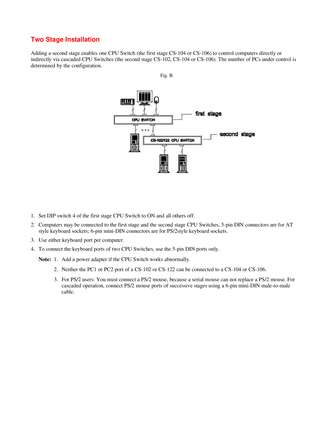
Adding a second stage enables one CPU Switch (the first stage
Fig. B
1.Set DIP switch 4 of the first stage CPU Switch to ON and all others off.
2.Computers may be connected to the first stage and the second stage CPU Switches.
3.Use either keyboard port per computer.
4.To connect the keyboard ports of two CPU Switches, use the
2.Neither the PC1 or PC2 port of a
3.For PS/2 users: You must connect a PS/2 mouse, because a serial mouse can not replace a PS/2 mouse. For cascaded operation, connect PS/2 mouse ports of successive stages using a