Installing the Blade
TURN OFF TOOL AND DISCONNECT FROM POWER SUPPLY.
DO NOT CUT FERROUS METAL (THAT WITH AN IRON OR STEEL CONTENT) OR MASONRY WITH THIS MITER SAW.
1.With the saw arm in the upper position, raise the lower guard as far as possible.
2.Loosen (but do not remove) the guard bracket screw, shown in Figure 3 until the guard bracket can be raised enough to permit access to the blade screw.
3.Hold the lower guard up and depress the spindle lock button with one hand and use the supplied blade wrench in the other hand to loosen (clockwise) the left hand threaded blade screw. NOTE: To use the spindle lock, depress the button as shown and rotate the spindle by hand until you feel the lock engage. Continue to hold the lock button in to keep the spindle from turning.
4.Install the saw blade making sure that the teeth at the bottom edge of the blade are pointing toward the back of the saw (away from the operator).
5.Replace the outer blade washer and tighten the blade screw (counterclockwise) while holding the lower guard up and the spindle lock engaged with your other hand.
NEVER DEPRESS THE SPINDLE LOCK BUTTON WHILE THE BLADE IS ROTATING.
AFTER INSTALLING THE SAW BLADE, REPOSITION GUARD BRACKET MAKING SURE IT IS FULLY SEATED ON GUARD SCREW. FIRMLY TIGHTEN SCREW. FAILURE TO DO SO WILL CAUSE SERIOUS DAMAGE TO THE SAW.
Rear Lower Guard Adjustment
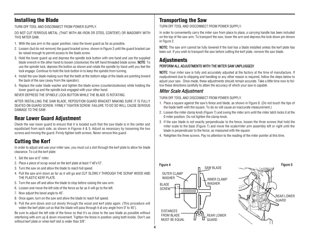
Check the rear lower guard to ensure that it is located such that the saw blade is in the center and equidistant from each side, as shown in Figures 4 & 5. Adjust as necessary by loosening the two screws and moving the guard. Firmly tighten both screws. Never remove this guard.
Cutting the Kerf
In order to adjust and use your miter saw, you must cut a slot through the kerf plate to allow for blade clearance. To cut the kerf plate:
Transporting the Saw
TURN OFF TOOL AND DISCONNECT FROM POWER SUPPLY.
In order to conveniently carry the miter saw from place to place, a carrying handle has been included on the top of the saw arm. To transport the saw, lower the arm and depress the lock down pin shown in Figure 2.
NOTE: The saw arm cannot be fully lowered if the tool has a blade installed unless the kerf plate has been cut. If you wish to transport the saw before cutting the kerf plate, remove the saw blade.
Adjustments
PERFORM ALL ADJUSTMENTS WITH THE MITER SAW UNPLUGGED!
NOTE: Your miter saw is fully and accurately adjusted at the factory at the time of manufacture. If readjustment due to shipping and handling or any other reason is required, follow the steps below to adjust your saw. Once made, these adjustments should remain accurate. Take a little time now to fol- low these directions carefully to attain the accuracy of which your saw is capable.
Miter Scale Adjustment
TURN OFF TOOL AND DISCONNECT FROM POWER SUPPLY.
1.Place a square against the saw’s fence and blade, as shown in Figure 6. (Do not touch the tips of the blade teeth with the square. To do so will cause an inaccurate measurement.)
2.Loosen the miter clamp knob (Figure 7) and swing the miter arm until the miter latch locks it at the 0 miter position. Do not tighten the clamp knob.
3.If the saw blade is not exactly perpendicular to the fence, loosen the three screws that hold the miter scale to the base (Figure 7) and move the scale/miter arm assembly left or right until the blade is perpendicular to the fence, as measured with the square.
4.Retighten the three screws. Pay no attention to the reading of the miter pointer at this time.
1.Set the saw at 0˚ miter.
2.Place a piece of scrap wood on the kerf plate at least 1"x6"x12".
3.Turn the saw on and allow the blade to reach full speed.
4.Pull the saw arm down as far as it will go and CUT SLOWLY THROUGH THE SCRAP WOOD AND THE PLASTIC KERF PLATE.
5.Turn the saw off and allow the blade to stop before raising the saw arm.
6.Loosen and move the left side of the fence as far as it will go to the left.
7.Now adjust the bevel angle to 45˚.
8.Once again, turn on the saw and allow the blade to reach full speed.
9.Pull the arm down and cut slowly through the wood and kerf plate again. (This procedure will widen the kerf plate cut so that the blade will pass through it at any angle from 0˚ to 45˚).
Be sure to adjust the left side of the fence so that it’s as close to the saw blade as possible without interfering with arm up & down movement. Tighten the fence in position using both knobs. Don’t use without kerf plate or when kerf slot is wider than 3/8”.
Figure 4
OUTER CLAMP
WASHER ![]()
BLADE |
SCREW |
DISTANCES
FROM BLADE
MUST BE EQUAL
SAW BLADE
INNER CLAMP WASHER
REAR LOWER GUARD
Figure 5
REAR LOWER GUARD
4