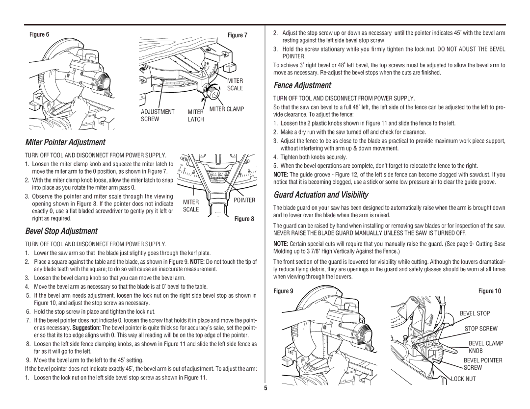
Figure 6
45 | 40 | 35 | 30 | 25 | 20 |
ADJUSTMENT MITER
SCREWLATCH
Figure 7
45 ![]()
![]() 40
40 ![]() 35
35 ![]()
3 0 ![]()
MITER
SCALE
MITER CLAMP
2.Adjust the stop screw up or down as necessary until the pointer indicates 45˚ with the bevel arm resting against the left side bevel stop screw.
3.Hold the screw stationary while you firmly tighten the lock nut. DO NOT ADUST THE BEVEL POINTER.
To achieve 3˚ right bevel or 48˚ left bevel, the top screws must be adjusted to allow the bevel arm to move as necessary.
Fence Adjustment
TURN OFF TOOL AND DISCONNECT FROM POWER SUPPLY.
So that the saw can bevel to a full 48˚ left, the left side of the fence can be adjusted to the left to pro- vide clearance. To adjust the fence:
1. | Loosen the 2 plastic knobs shown in Figure 11 and slide the fence to the left. |
2. | Make a dry run with the saw turned off and check for clearance. |
Miter Pointer Adjustment
TURN OFF TOOL AND DISCONNECT FROM POWER SUPPLY.
1.Loosen the miter clamp knob and squeeze the miter latch to move the miter arm to the 0 position, as shown in Figure 7.
2.With the miter clamp knob loose, allow the miter latch to snap into place as you rotate the miter arm pass 0.
3.Observe the pointer and miter scale through the viewing opening shown in Figure 8. If the pointer does not indicate exactly 0, use a flat bladed screwdriver to gently pry it left or right as required.
22.5
85 |
|
5 | 80 |
| 10 |
MITER
SCALE
4
|
|
|
|
|
|
|
| 50 |
70 |
|
|
|
|
| 0 | 55 | 5 |
1 | 1 | 65 | 1 | 1 | 40 | 4 | ||
| 2 | 2 |
|
| ||||
|
|
| 25 |
|
|
|
| |
|
|
|
|
|
|
|
|
POINTER
Figure 8
3. | Adjust the fence to be as close to the blade as practical to provide maximum work piece support, |
| without interfering with arm up & down movement. |
4. | Tighten both knobs securely. |
5. | When the bevel operations are complete, don’t forget to relocate the fence to the right. |
NOTE: The guide groove - Figure 12, of the left side fence can become clogged with sawdust. If you notice that it is becoming clogged, use a stick or some low pressure air to clear the guide groove.
Guard Actuation and Visibility
The blade guard on your saw has been designed to automatically raise when the arm is brought down and to lower over the blade when the arm is raised.
The guard can be raised by hand when installing or removing saw blades or for inspection of the saw.
Bevel Stop Adjustment
TURN OFF TOOL AND DISCONNECT FROM POWER SUPPLY.
1.Lower the saw arm so that the blade just slightly goes through the kerf plate.
2.Place a square against the table and the blade, as shown in Figure 9. NOTE: Do not touch the tip of any blade teeth with the square; to do so will cause an inaccurate measurement.
3.Loosen the bevel clamp knob so that you can move the bevel arm.
4.Move the bevel arm as necessary so that the blade is at 0˚ bevel to the table.
5.If the bevel arm needs adjustment, loosen the lock nut on the right side bevel stop as shown in Figure 10, and adjust the stop screw as necessary.
6.Hold the stop screw in place and tighten the lock nut.
7.If the bevel pointer does not indicate 0, loosen the screw that holds it in place and move the point- er as necessary. Suggestion: The bevel pointer is quite thick so for accuracy’s sake, set the point- er so that its top edge aligns with 0. This way all reading will be on the top edge of the pointer.
8.Loosen the left side fence clamping knobs, as shown in Figure 11 and slide the left side fence as far as it will go to the left.
9.Move the bevel arm to the left to the 45˚ setting.
If the bevel pointer does not indicate exactly 45˚, the bevel arm is out of adjustment. To adjust the arm: 1. Loosen the lock nut on the left side bevel stop screw as shown in Figure 11.
NEVER RAISE THE BLADE GUARD MANUALLY UNLESS THE SAW IS TURNED OFF.
NOTE: Certain special cuts will require that you manually raise the guard. (See page 9- Cutting Base Molding up to 3 7/8" High Vertically Against the Fence.)
The front section of the guard is louvered for visibility while cutting. Although the louvers dramatical- ly reduce flying debris, they are openings in the guard and safety glasses should be worn at all times when viewing through the louvers.
Figure 9 | Figure 10 |
BEVEL STOP
STOP SCREW
BEVEL CLAMP
KNOB
BEVEL POINTER
SCREW
LOCK NUT
5