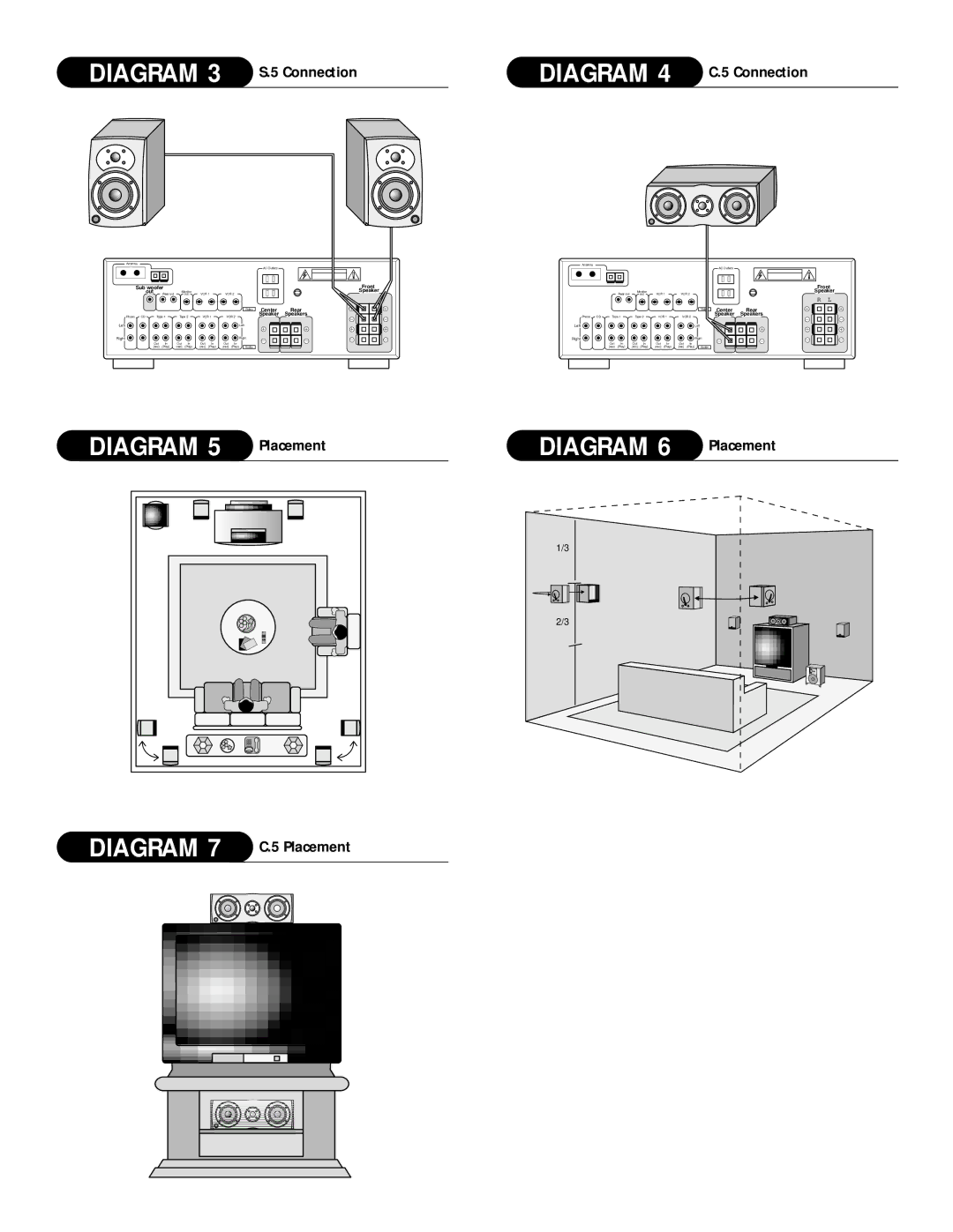
5, P.5, S.5, C.5 specifications
Athena Technologies has established itself as a leader in the field of sophisticated electronic systems and cutting-edge technologies. Among its standout products are the AS-P300, C.5, S.5, and AS-P400, which showcase an impressive array of features and capabilities designed to meet the demands of various applications.The AS-P300 is designed with flexibility and efficiency in mind. It boasts a robust processing unit capable of handling complex computations, making it ideal for high-performance applications. The system supports a wide range of connectivity options, ensuring seamless integration with existing infrastructure. Notably, its modular architecture allows users to customize configurations based on specific project requirements, enhancing its versatility.
The C.5 series stands out with its focus on compactness and energy efficiency. It incorporates advanced power management technologies, significantly reducing energy consumption without compromising performance. The C.5 is particularly suitable for mobile applications, where space and power are at a premium. Featuring state-of-the-art thermal management systems, it ensures optimal performance even under demanding conditions.
On the other hand, the S.5 system emphasizes scalability, making it ideal for growing enterprises. With its expandable architecture, organizations can easily scale up their operations without needing to overhaul existing systems. The S.5 employs advanced data processing algorithms, enabling real-time analytics and decision-making capabilities that are crucial for modern business environments.
Finally, the AS-P400 represents the pinnacle of Athena Technologies’ offerings. It integrates all the best features of its predecessors while introducing groundbreaking technologies such as artificial intelligence and machine learning capabilities. This system is designed for more complex tasks, providing users with predictive analytics and automated decision-making tools that streamline operations and enhance productivity.
These products collectively exemplify Athena Technologies' commitment to innovation and quality. Their emphasis on modularity, energy efficiency, scalability, and advanced features positions them as ideal solutions for a range of industries, including telecommunications, healthcare, and manufacturing. Customers can expect reliability and cutting-edge performance from these systems, ensuring that they remain at the forefront of technological advancement in their respective fields.

