Rear Panel
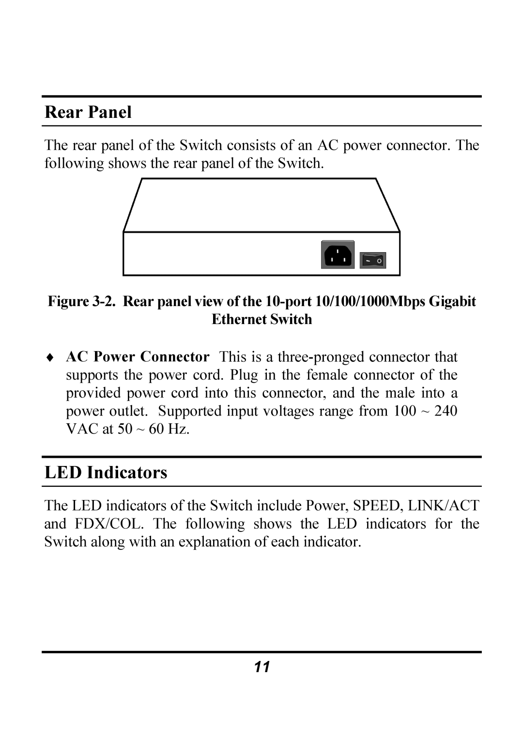
The rear panel of the Switch consists of an AC power connector. The following shows the rear panel of the Switch.
Figure 3-2. Rear panel view of the 10-port 10/100/1000Mbps Gigabit
Ethernet Switch
♦AC Power Connector This is a
LED Indicators
The LED indicators of the Switch include Power, SPEED, LINK/ACT and FDX/COL. The following shows the LED indicators for the Switch along with an explanation of each indicator.
11