|
| Electrical Safety Analyzer |
|
| Performing Electrical Safety Tests |
| Performing a Current Consumption Test | Which leakage tests are available depends on which |
| To measure the current consumed by the DUT, press | standard is selected. See the Selecting the Test Standard |
| section earlier in this manual to change the standard the | |
| A. The Analyzer displays the current flowing through | |
| Analyzer is using. | |
| the mains connections of the test receptacle. | |
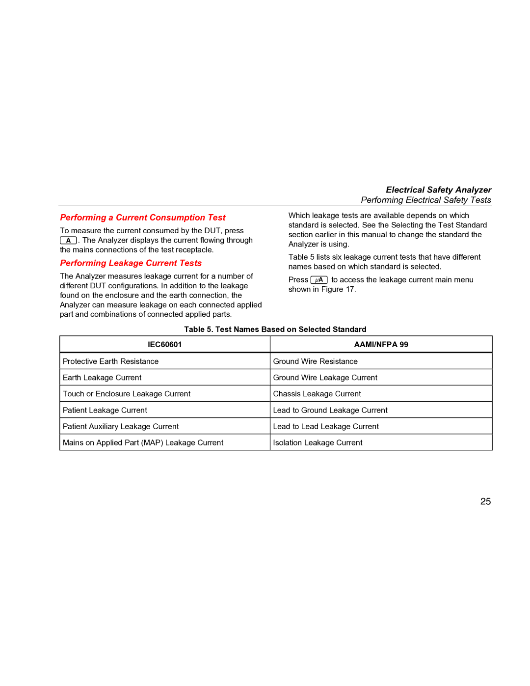
| Table 5 lists six leakage current tests that have different | |
| Performing Leakage Current Tests | |
| names based on which standard is selected. | |
| The Analyzer measures leakage current for a number of | |
| Press Bto access the leakage current main menu | |
| different DUT configurations. In addition to the leakage | |
| shown in Figure 17. | |
| found on the enclosure and the earth connection, the | |
|
| |
| Analyzer can measure leakage on each connected applied |
|
| part and combinations of connected applied parts. |
|
| Table 5. Test Names Based on Selected Standard | |
| IEC60601 | AAMI/NFPA 99 |
|
|
|
| Protective Earth Resistance | Ground Wire Resistance |
|
|
|
| Earth Leakage Current | Ground Wire Leakage Current |
|
|
|
| Touch or Enclosure Leakage Current | Chassis Leakage Current |
|
|
|
| Patient Leakage Current | Lead to Ground Leakage Current |
|
|
|
| Patient Auxiliary Leakage Current | Lead to Lead Leakage Current |
|
|
|
| Mains on Applied Part (MAP) Leakage Current | Isolation Leakage Current |
|
|
|
25
