ESA612
Users Manual
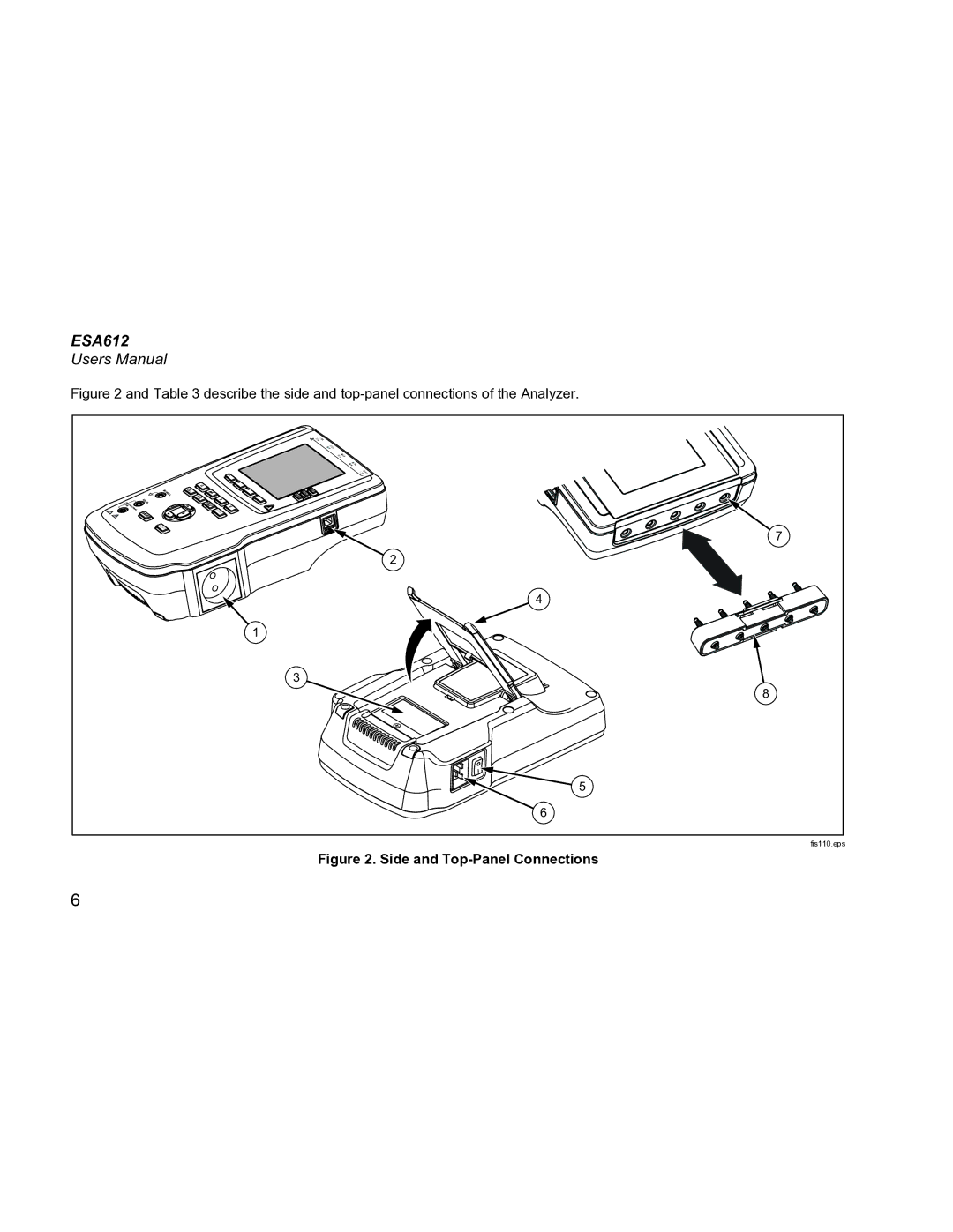
Figure 2 and Table 3 describe the side and top-panel connections of the Analyzer.
R RA |
|
F LL |
|
L LA |
|
N RL |
|
C1 | V1 |
TEST | 7 |
| |
| 2 |
| 4 |
1 |
|
3 | 8 |
| |
| 5 |
| 6 |
| fis110.eps |
Figure 2. Side and Top-Panel Connections
6