| Decoder for Atlas N Scale |
| 9 |
| ||
|
|
|
|
|
| |
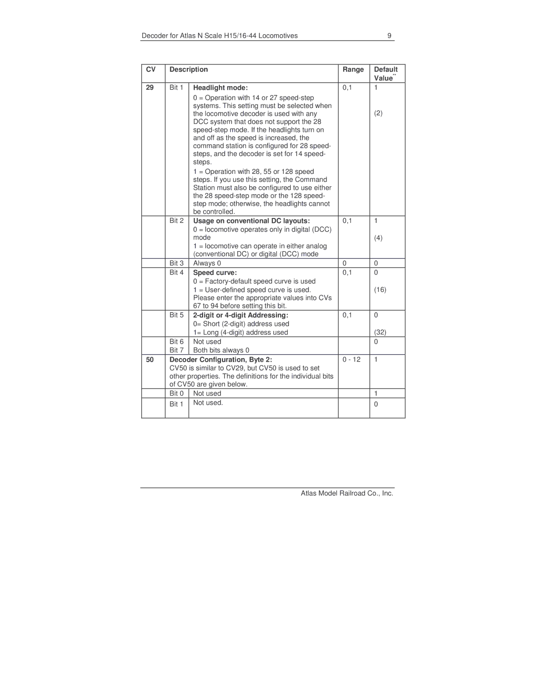
| CV | Description | Range | Default | ||
|
|
|
|
| Value** | |
| 29 | Bit 1 | Headlight mode: | 0,1 | 1 |
|
|
|
| 0 = Operation with 14 or 27 |
|
|
|
|
|
| systems. This setting must be selected when |
| (2) |
|
|
|
| the locomotive decoder is used with any |
|
| |
|
|
| DCC system that does not support the 28 |
|
|
|
|
|
|
|
|
| |
|
|
| and off as the speed is increased, the |
|
|
|
|
|
| command station is configured for 28 speed- |
|
|
|
|
|
| steps, and the decoder is set for 14 speed- |
|
|
|
|
|
| steps. |
|
|
|
|
|
| 1 = Operation with 28, 55 or 128 speed |
|
|
|
|
|
| steps. If you use this setting, the Command |
|
|
|
|
|
| Station must also be configured to use either |
|
|
|
|
|
| the 28 |
|
|
|
|
|
| step mode; otherwise, the headlights cannot |
|
|
|
|
|
| be controlled. |
|
|
|
|
| Bit 2 | Usage on conventional DC layouts: | 0,1 | 1 |
|
|
|
| 0 = locomotive operates only in digital (DCC) |
|
|
|
|
|
| mode |
| (4) |
|
|
|
| 1 = locomotive can operate in either analog |
|
|
|
|
|
| (conventional DC) or digital (DCC) mode |
|
|
|
|
| Bit 3 | Always 0 | 0 | 0 |
|
|
| Bit 4 | Speed curve: | 0,1 | 0 |
|
|
|
| 0 = |
| (16) |
|
|
|
| 1 = |
|
| |
|
|
| Please enter the appropriate values into CVs |
|
|
|
|
|
| 67 to 94 before setting this bit. |
|
|
|
|
| Bit 5 |
| 0,1 | 0 |
|
|
|
| 0= Short |
| (32) |
|
|
|
| 1= Long |
|
| |
|
| Bit 6 | Not used |
| 0 |
|
|
| Bit 7 | Both bits always 0 |
|
|
|
| 50 | Decoder Configuration, Byte 2: | 0 - 12 | 1 |
| |
|
| CV50 is similar to CV29, but CV50 is used to set |
|
|
| |
|
| other properties. The definitions for the individual bits |
|
|
| |
|
| of CV50 are given below. |
|
|
| |
|
| Bit 0 | Not used |
| 1 |
|
|
| Bit 1 | Not used. |
| 0 |
|
|
|
|
|
|
|
|
Atlas Model Railroad Co., Inc.