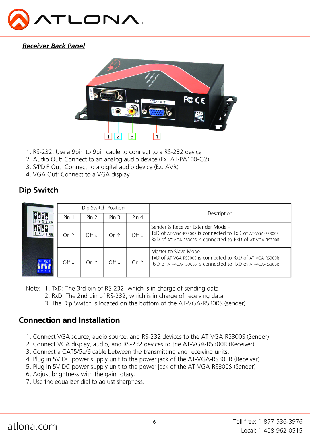
Receiver Back Panel
1 ![]()
![]() 2
2
3
4
1.
2.Audio Out: Connect to an analog audio device (Ex.
3.S/PDIF Out: Connect to a digital audio device (Ex. AVR)
4.VGA Out: Connect to a VGA display
Dip Switch
| Dip Switch Position |
| Description | ||
|
|
|
| ||
Pin 1 | Pin 2 | Pin 3 | Pin 4 | ||
| |||||
|
|
|
|
| |
|
|
|
| Sender & Receiver Extender Mode - | |
On h | Off i | On h | Off i | TxD of | |
RxD of | |||||
|
|
|
| ||
|
|
|
|
| |
|
|
|
| Master to Slave Mode - | |
Off i | On h | Off i | On h | TxD of | |
RxD of | |||||
|
|
|
| ||
|
|
|
|
| |
Note: 1. TxD: The 3rd pin of
2.RxD: The 2nd pin of
3.The Dip Switch is located on the bottom of the
Connection and Installation
1.Connect VGA source, audio source, and
2.Connect VGA display, audio, and
3.Connect a CAT5/5e/6 cable between the transmitting and receiving units.
4.Plug in 5V DC power supply unit to the power jack of the
5.Plug in 5V DC power supply unit to the power jack of the
6.Adjust brightness with the gain rotary.
7.Use the equalizer dial to adjust sharpness.
atlona.com | 6 | Toll free: |
| Local: |
