Appendix A – Configuration Straps
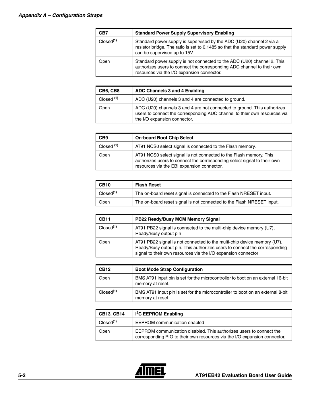
CB7 | Standard Power Supply Supervisory Enabling |
|
|
Closed(1) | Standard power supply is supervised by the ADC (U20) channel 2 via a |
| resistor bridge. The ratio is set to 0.1485 so that the standard power supply |
| can be supervised up to 15V. |
|
|
Open | Standard power supply is not connected to the ADC (U20) channel 2. This |
| authorizes users to connect the corresponding ADC channel to their own |
| resources via the I/O expansion connector. |
|
|
CB6, CB8 | ADC Channels 3 and 4 Enabling |
|
|
Closed (1) | ADC (U20) channels 3 and 4 are connected to ground. |
Open | ADC (U20) channels 3 and 4 are not connected to ground. This authorizes |
| users to connect the corresponding ADC channel to their own resources via |
| the I/O expansion connector. |
|
|
CB9 |
|
|
|
Closed (1) | AT91 NCS0 select signal is connected to the Flash memory. |
Open | AT91 NCS0 select signal is not connected to the Flash memory. This |
| authorizes users to connect the corresponding select signal to their own |
| resources via the EBI expansion connector. |
|
|
CB10 | Flash Reset |
|
|
Closed(1) | The |
Open | The |
|
|
|
|
CB11 | PB22 Ready/Busy MCM Memory Signal |
|
|
Closed(1) | AT91 PB22 signal is connected to the |
| Ready/Busy output pin |
|
|
Open | AT91 PB22 signal is not connected to the |
| Ready/Busy output pin. This authorizes users to connect the corresponding |
| signal to their own resources via the I/O expansion connector |
|
|
|
|
CB12 | Boot Mode Strap Configuration |
|
|
Open | BMS AT91 input pin is set for the microcontroller to boot on an external |
| memory at reset. |
|
|
Closed(1) | BMS AT91 input pin is set for the microcontroller to boot on an external |
| memory at reset. |
|
|
|
|
CB13, CB14 | I2C EEPROM Enabling |
Closed(1) | EEPROM communication enabled |
Open | EEPROM communication disabled. This authorizes users to connect the |
| corresponding PIO to their own resources via the I/O expansion connector. |
|
|
AT91EB42 Evaluation Board User Guide