®
3


12-Volt
Navigation Lights
Sidelights: 5040, 5045, 5080
Installation Instructions
SAVE THESE INSTRUCTIONS
Form Number 69379 Rev. B |
FEATURES
The Attwood Pulsar Navigation Lights are designed for boats upto 39.6 ft. (12 meters). They feature impact resistant,
REQUIRED FOR INSTALLATION
•Cordless drill with 1/8", 3/8", and 3/4" (3, 10, and 19mm) bits.
•Screwdriver.
•Two #8 or #10 stainless pan head screws per light.
•
![]() WARNING:
WARNING:
To prevent personal injury, disconnect the power source when installing or servicing this product. Always remove the boat from the water before using 120V AC power tools.
LOCATION (All-Round Lights)
Important: Before drilling mounting holes, be sure that light shines within 5° of horizontal when the boat is floating.
Figure 1
One meter or
LOCATION (Sidelights)
Mount sidelights to a smooth surface on the gunwale, deck or superstructure where the light beam will not be obstructed. Position Bi- Color combination light as far forward as possible. (Figure 2)
Important: Before drilling mounting holes, be sure sidelights shine straight ahead and that they shine within 5° of horizontal when the boat is floating.
Figure 2
Red | Green | Red | Green |
(Port) | (Starboard) | (Port) | (Starboard) |
INSTALLATION, DECK MOUNT
All-Round Lights
1.To access mounting holes, gently twist lens helmet counterclockwise to remove.
2.Place light in position as shown in Figure 1.
Important: Before drilling, be sure that light will shine within 5° of horizontal when boat is floating.
3.Mark and drill 3/4" (19mm) diameter hole. (Figure 3)
4.Thread wire leads and base stem into hole. Mark location of screw holes. Proceed to Step 5 below.
Bi-Color Sidelights and Sidelight Pairs
1.To access mounting holes, gently twist lens helmet counterclockwise to remove.
2.Place sidelight(s) in position as shown in Figure 2.
Important: Before drilling, be sure that sidelights will shine straight ahead and within 5° of horizontal when boat is floating.
3.For
4.Thread wire leads and base stem into hole. Align centerline mark with
5.Remove base and drill 1/8" (3mm) pilot holes for both screws.
6.Bring 12V DC (+) and
7.Activate light to verify proper operation.
8.Apply a thin bead of
9.Align and fasten base with stainless screws. Do not over tighten.
10.Replace lens helmet flush on base and turn clockwise until click is heard and felt. (Figure 3)
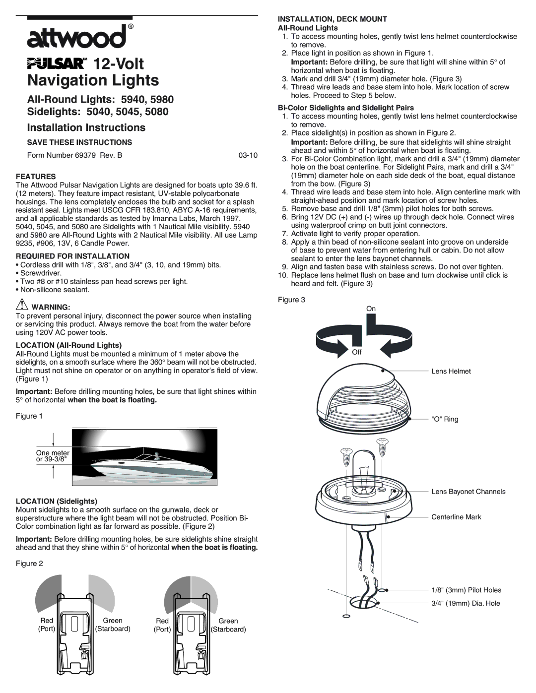
Figure 3
On
Off
•Lens Helmet
• | "O" Ring |
•Lens Bayonet Channels
•Centerline Mark
•1/8" (3mm) Pilot Holes
• | 3/4" (19mm) Dia. Hole |