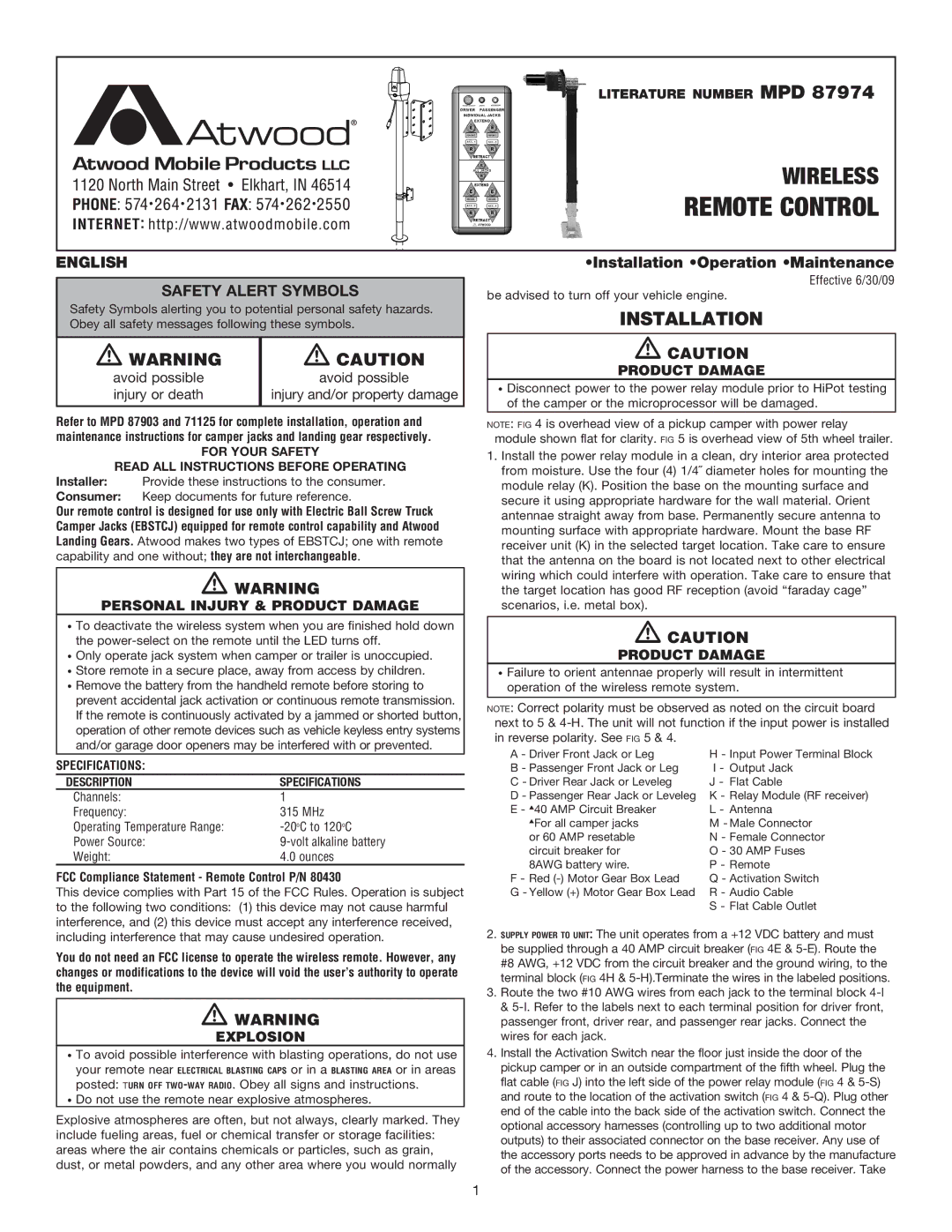
literature number MPD 87974
WIRELESS
Remote Control
ENGLISH
Safety alert symbols
Safety Symbols alerting you to potential personal safety hazards. Obey all safety messages following these symbols.
m warning | m caution |
avoid possible | avoid possible |
injury or death | injury and/or property damage |
|
|
•Installation •Operation •Maintenance
Effective 6/30/09
be advised to turn off your vehicle engine.
installation
mcaution
product damage
•Disconnect power to the power relay module prior to HiPot testing of the camper or the microprocessor will be damaged.
Refer to MPD 87903 and 71125 for complete installation, operation and maintenance instructions for camper jacks and landing gear respectively.
For your safety
read all instructions before operating
Installer: Provide these instructions to the consumer.
Consumer: Keep documents for future reference.
Our remote control is designed for use only with Electric Ball Screw Truck Camper Jacks (EBSTCJ) equipped for remote control capability and Atwood Landing Gears. Atwood makes two types of EBSTCJ; one with remote capability and one without; they are not interchangeable.
mwarning
Personal injury & product damage
•To deactivate the wireless system when you are finished hold down the
•Only operate jack system when camper or trailer is unoccupied.
•Store remote in a secure place, away from access by children.
•Remove the battery from the handheld remote before storing to prevent accidental jack activation or continuous remote transmission. If the remote is continuously activated by a jammed or shorted button, operation of other remote devices such as vehicle keyless entry systems and/or garage door openers may be interfered with or prevented.
SPECIFICATIONS: |
|
description | specifications |
Channels: | 1 |
Frequency: | 315 MHz |
Operating Temperature Range: | |
Power Source: | |
Weight: | 4.0 ounces |
FCC Compliance Statement - Remote Control P/N 80430
This device complies with Part 15 of the FCC Rules. Operation is subject to the following two conditions: (1) this device may not cause harmful interference, and (2) this device must accept any interference received, including interference that may cause undesired operation.
You do not need an FCC license to operate the wireless remote. However, any changes or modifications to the device will void the user’s authority to operate the equipment.
mwarning
explosion
•To avoid possible interference with blasting operations, do not use
your remote near electrical blasting caps or in a blasting area or in areas
posted: turn off
•Do not use the remote near explosive atmospheres.
Explosive atmospheres are often, but not always, clearly marked. They include fueling areas, fuel or chemical transfer or storage facilities: areas where the air contains chemicals or particles, such as grain, dust, or metal powders, and any other area where you would normally
note: fig 4 is overhead view of a pickup camper with power relay module shown flat for clarity. fig 5 is overhead view of 5th wheel trailer.
1.Install the power relay module in a clean, dry interior area protected from moisture. Use the four (4) 1/4˝ diameter holes for mounting the module relay (K). Position the base on the mounting surface and secure it using appropriate hardware for the wall material. Orient antennae straight away from base. Permanently secure antenna to mounting surface with appropriate hardware. Mount the base RF receiver unit (K) in the selected target location. Take care to ensure that the antenna on the board is not located next to other electrical wiring which could interfere with operation. Take care to ensure that the target location has good RF reception (avoid “faraday cage” scenarios, i.e. metal box).
mcaution
product damage
•Failure to orient antennae properly will result in intermittent operation of the wireless remote system.
note: Correct polarity must be observed as noted on the circuit board next to 5 &
A - Driver Front Jack or Leg | H - Input Power Terminal Block |
B - Passenger Front Jack or Leg | I - Output Jack |
C - Driver Rear Jack or Leveleg | J - Flat Cable |
D - Passenger Rear Jack or Leveleg | K - Relay Module (RF receiver) |
E - s40 AMP Circuit Breaker | L - Antenna |
sFor all camper jacks | M - Male Connector |
or 60 AMP resetable | N - Female Connector |
circuit breaker for | O - 30 AMP Fuses |
8AWG battery wire. | P - Remote |
F - Red | Q - Activation Switch |
G - Yellow (+) Motor Gear Box Lead | R - Audio Cable |
| S - Flat Cable Outlet |
2.supply power to unit: The unit operates from a +12 VDC battery and must be supplied through a 40 AMP circuit breaker (fig 4E &
3.Route the two #10 AWG wires from each jack to the terminal block
4.Install the Activation Switch near the floor just inside the door of the pickup camper or in an outside compartment of the fifth wheel. Plug the flat cable (fig J) into the left side of the power relay module (fig 4 &
1