RT850 specifications
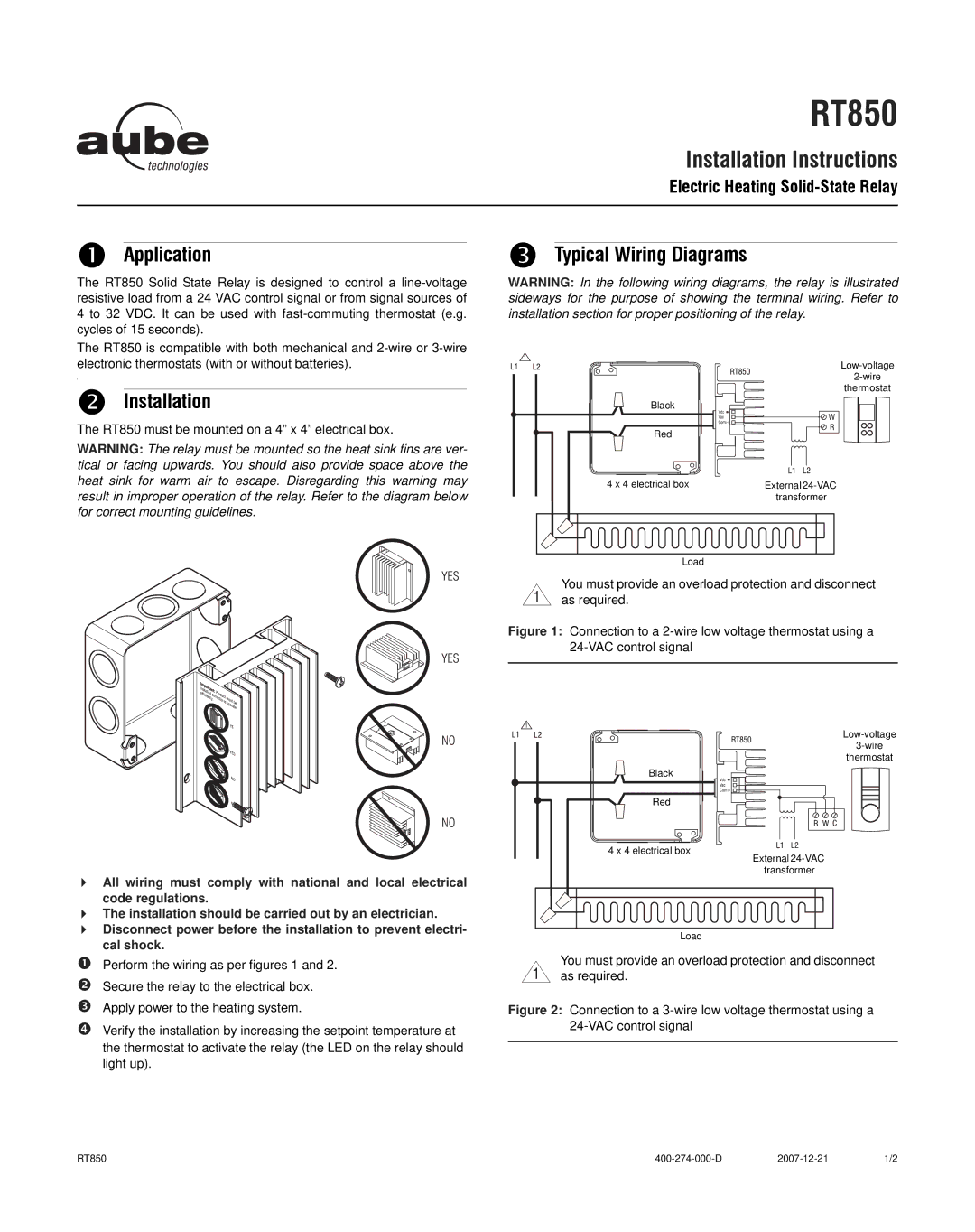
Aube Technologies RT850 is an innovative smart thermostat designed for residential heating and cooling systems. This device is engineered to provide optimal temperature control while promoting energy efficiency and comfort in the home. With a sleek and modern design, the RT850 not only enhances the aesthetics of any living space but also offers a range of advanced features that cater to the needs of today's homeowners.One of the standout features of the RT850 is its user-friendly interface. The large, easy-to-read display allows users to navigate through settings effortlessly, making adjustments to their home’s temperature a breeze. The thermostat supports both touch and physical buttons, providing flexibility in operation. This dual functionality caters to diverse user preferences, ensuring that everyone can operate the device with ease.
The RT850 uses advanced temperature control algorithms, enabling it to learn the homeowner's heating and cooling patterns over time. This adaptive learning capability allows the thermostat to create personalized schedules that optimize energy usage and maintain comfort levels. Additionally, the smart thermostat is equipped with a Wi-Fi connection, allowing users to control their home's climate remotely via a smartphone app. This connectivity makes it convenient to adjust settings while away from home, ensuring that the environment is just right upon returning.
Another significant characteristic of the Aube RT850 is its compatibility with various HVAC systems, including conventional, heat pump, and electric baseboard heating. This versatility allows it to be an ideal choice for different home setups. Furthermore, the device supports multiple stage heating and cooling, making it suitable for complex climate control systems.
Energy efficiency is a core feature of the RT850. By utilizing innovative technologies, the thermostat can track energy usage and provide homeowners with insights into their consumption patterns, promoting more eco-friendly choices. The device also includes a built-in energy-saving mode that automatically adjusts settings to reduce unnecessary energy expenditure when the house is unoccupied.
In summary, Aube Technologies RT850 stands out as a top choice for homeowners seeking a reliable, energy-efficient thermostat. With its intuitive interface, smart features, and broad compatibility, the RT850 is well-equipped to enhance comfort and streamline energy management in any residence.

