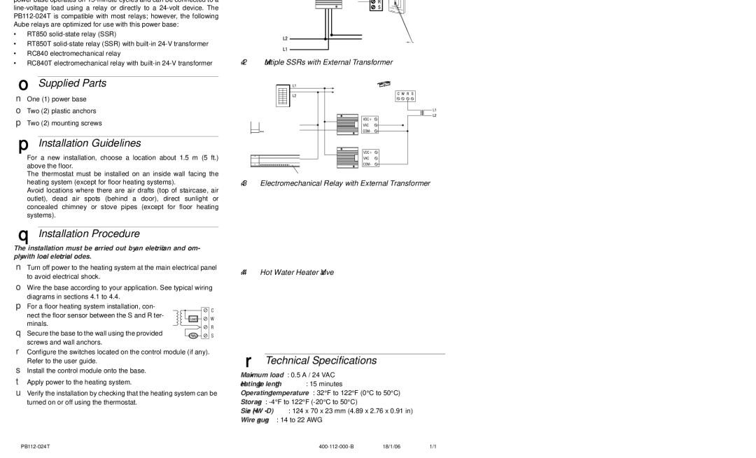
TH113 A, TH113 specifications
Aube Technologies is renowned for its innovative approach to temperature control solutions, and the TH113 A and TH113 are prime examples of their commitment to quality and performance. These thermostats are designed to efficiently manage heating and cooling systems in residential or commercial settings, providing users with comfort while optimizing energy usage.One of the standout features of the Aube Technologies TH113 A and TH113 is their user-friendly interface. These devices are equipped with a large, easy-to-read display that allows users to monitor temperature settings and program schedules effortlessly. The simple layout makes it accessible for individuals of all technical backgrounds, ensuring that anyone can operate the device without confusion.
The TH113 series incorporates advanced technology that enables precise temperature control. With a built-in programmable function, users can easily set different temperatures according to their daily routines. This capability not only enhances comfort but also leads to significant energy savings, as the system can automatically lower or raise temperatures depending on occupancy.
Another notable characteristic of the Aube Technologies TH113 is its compatibility with various heating and cooling systems. Whether you have electric baseboard heating, radiant floor heating, or a conventional HVAC system, the TH113 series can integrate seamlessly, making it a versatile choice for homeowners and business owners alike. This adaptability means it can cater to diverse applications, simplifying installations and reducing the need for multiple devices.
Moreover, both models in the TH113 line are equipped with a built-in energy-saving feature. This function allows users to monitor energy consumption over time, enabling them to make informed decisions about their energy use. With the push for sustainability and cost-effectiveness in mind, this feature ensures that users can track savings and optimize their consumption patterns.
The aesthetic design of the TH113 series is another advantage. With a sleek, modern look, these thermostats will blend well with various interior designs. Their compact size and unobtrusive style make them a stylish addition to any room, enhancing rather than detracting from the overall decor.
In summary, Aube Technologies TH113 A and TH113 represent exemplary advancements in thermostat technology. They offer user-friendly operation, precise temperature control, compatibility with multiple systems, energy-saving features, and a modern design. The combination of these attributes positions them as ideal solutions for those looking to enhance their living or working environments while maintaining energy efficiency.

