Power Connections

The switching power supply is designed to operate properly from any AC power source 100–240V, 50/60 Hz without user adjustment. Simply connect the receiver to a standard AC power outlet, using only an IEC 320-type input cordset approved for the country of use. Power to the unit is controlled by the front-panel Power switch.

An auxiliary AC “jumper” (pass-through) outlet is provided on the rear panel, and a ”jumper” power cordset is included, to simplify power connections by “daisy-chaining” together an array of AEW receivers and antenna distribution units. Maximum output from the auxiliary AC outlet is 500 watts; it is fused internally. Do not exceed the 500W power limit. Do not connect high-current devices, such as power amplifiers, to this outlet.

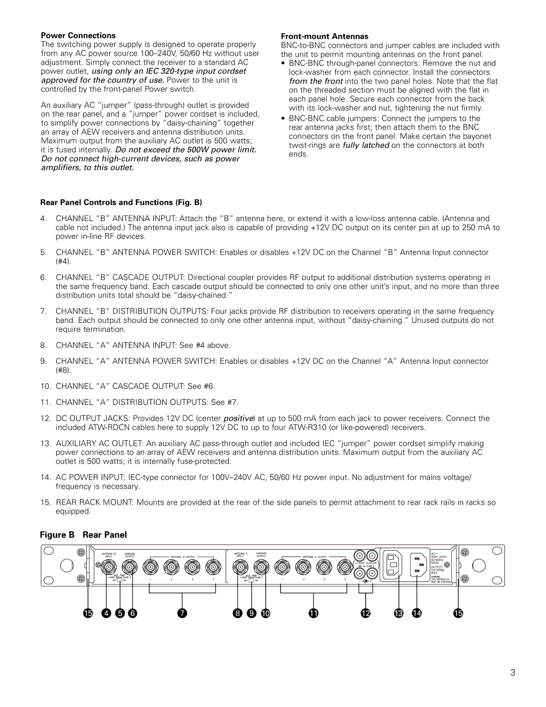
Rear Panel Controls and Functions (Fig. B)

Front-mount Antennas

BNC-to-BNC connectors and jumper cables are included with the unit to permit mounting antennas on the front panel.

BNC-BNC through-panel connectors: Remove the nut and lock-washer from each connector. Install the connectors from the front into the two panel holes. Note that the flat on the threaded section must be aligned with the flat in each panel hole. Secure each connector from the back with its lock-washer and nut, tightening the nut firmly.

BNC-BNC cable jumpers: Connect the jumpers to the rear antenna jacks first; then attach them to the BNC connectors on the front panel. Make certain the bayonet twist-rings are fully latched on the connectors at both ends.

4.CHANNEL “B” ANTENNA INPUT: Attach the “B” antenna here, or extend it with a low-loss antenna cable. (Antenna and cable not included.) The antenna input jack also is capable of providing +12V DC output on its center pin at up to 250 mA to power in-line RF devices.

5.CHANNEL “B” ANTENNA POWER SWITCH: Enables or disables +12V DC on the Channel “B” Antenna Input connector (#4).

6.CHANNEL “B” CASCADE OUTPUT: Directional coupler provides RF output to additional distribution systems operating in the same frequency band. Each cascade output should be connected to only one other unit’s input, and no more than three distribution units total should be “daisy-chained.”

7.CHANNEL “B” DISTRIBUTION OUTPUTS: Four jacks provide RF distribution to receivers operating in the same frequency band. Each output should be connected to only one other antenna input, without “daisy-chaining.” Unused outputs do not require termination.

8.CHANNEL “A” ANTENNA INPUT: See #4 above.

9.CHANNEL “A” ANTENNA POWER SWITCH: Enables or disables +12V DC on the Channel “A” Antenna Input connector (#8).

10.CHANNEL “A” CASCADE OUTPUT: See #6.

11.CHANNEL “A” DISTRIBUTION OUTPUTS: See #7.

12.DC OUTPUT JACKS: Provides 12V DC (center positive) at up to 500 mA from each jack to power receivers. Connect the included ATW-RDCN cables here to supply 12V DC to up to four ATW-R310 (or like-powered) receivers.

13.AUXILIARY AC OUTLET: An auxiliary AC pass-through outlet and included IEC “jumper” power cordset simplify making power connections to an array of AEW receivers and antenna distribution units. Maximum output from the auxiliary AC outlet is 500 watts; it is internally fuse-protected.

14.AC POWER INPUT: IEC-type connector for 100V–240V AC, 50/60 Hz power input. No adjustment for mains voltage/ frequency is necessary.

15.REAR RACK MOUNT: Mounts are provided at the rear of the side panels to permit attachment to rear rack rails in racks so equipped.

Figure B Rear Panel


15

4

5

6


7


8


9

10


11


12

13

14


15


3

Page 3
Image 3
Audio-Technica AEW-DA550C, AEW-DA660D manual Figure B Rear Panel, Power Connections

AEW-DA660D, AEW-DA550C specifications

Audio-Technica is renowned for its high-quality audio equipment, and the AEW-DA660D and AEW-DA550C are prime examples of its commitment to excellence in wireless audio solutions. Both models showcase advanced technologies, making them ideal for professional applications such as live performances, broadcast events, and house of worship settings.

The AEW-DA660D is a dual-channel diversity antenna distribution system designed for use with Audio-Technica's wireless microphone systems. One of its standout features is its ability to provide robust RF signal distribution to up to six receivers, enhancing the reliability of wireless performances. The unit boasts a frequency range of 470-590 MHz and offers a total of six antenna outputs, which can be independently powered. This flexibility allows for optimal signal routing, ensuring high-quality audio transmission and reducing the risk of dropouts.

Incorporating cutting-edge technologies, the AEW-DA660D includes a low-noise amplifier that boosts signal integrity and minimizes distortion. The device is equipped with a versatile LED indicator that provides visual feedback on power status and signal strength, making it easier for sound engineers to monitor performance at a glance. The rugged construction of the AEW-DA660D makes it a durable option capable of withstanding the rigors of live events.

On the other hand, the AEW-DA550C performs a similar role as a four-channel antenna distribution system tailored for specific use with Audio-Technica's 5000 Series and other compatible wireless systems. With its 470-530 MHz frequency range, the AEW-DA550C supports seamless integration into existing setups. One of its key characteristics is the ability to distribute RF signals to four receivers, thereby streamlining the wireless microphone setup.

Both models boast high-quality BNC connectors, ensuring secure and reliable connections. They can be powered via the included 12V DC power supply, or through daisy-chain configurations, facilitating easy setup in various environments. Moreover, the compact design and user-friendly interface of the AEW-DA550C make it easy to transport and install, ensuring that sound professionals have everything they need for successful audio deployment.

Ultimately, the Audio-Technica AEW-DA660D and AEW-DA550C embody the brand's commitment to producing top-tier audio solutions, equipped with the technology and features that cater to the demanding needs of professional audio environments. Their reliability, flexibility, and ease of use make them indispensable tools for sound professionals worldwide.