WIRING INSTRUCTIONS
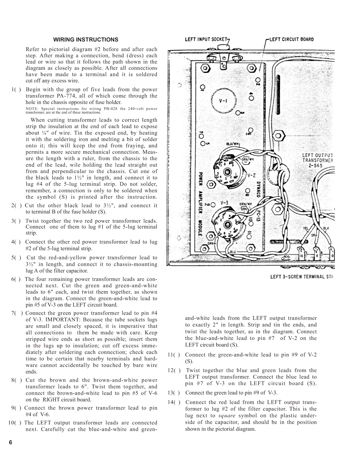
Refer to pictorial diagram #2 before and after each step. After making a connection, bend (dress) each lead or wire so that it follows the path shown in the diagram as closely as possible. After all connections have been made to a terminal and it is soldered cut off any excess wire.
1( ) Begin with the group of five leads from the power transformer
NOTE: Special instructions for wiring
When cutting transformer leads to correct length strip the insulation at the end of each lead to expose about ¼" of wire. Tin the exposed end, by heating it with the soldering iron and melting a bit of solder onto it; this will keep the end from fraying, and permits a more secure mechanical connection. Meas- ure the length with a ruler, from the chassis to the end of the lead, wile holding the lead straight out from and perpendicular to the chassis. Cut one of the black leads to 1½" in length, and connect it to lug #4 of the
2( ) Cut the other black lead to 3½", and connect it to terminal B of the fuse holder (S).
3( ) Twist together the two red power transformer leads. Connect one of them to lug #1 of the
4( ) Connect the other red power transformer lead to lug #2 of the
5( ) Cut the
6( ) The four remaining power transformer leads are con- nected next. Cut the green and
7( ) Connect the green power transformer lead to pin #4 of
8( ) Cut the brown and the
9( ) Connect the brown power transformer lead to pin #4 of
10( ) The LEFT output transformer leads are connected next. Carefully cut the
11( ) Connect the
(S).
12( ) Twist together the blue and green leads from the LEFT output transformer. Connect the blue lead to pin #7 of
13( ) Connect the green lead to pin #9 of
14( ) Connect the red lead from the LEFT output trans- former to lug #2 of the filter capacitor. This is the lug next to square symbol on the plastic under- side of the capacitor, and should be in the position shown in the pictorial diagram.
6