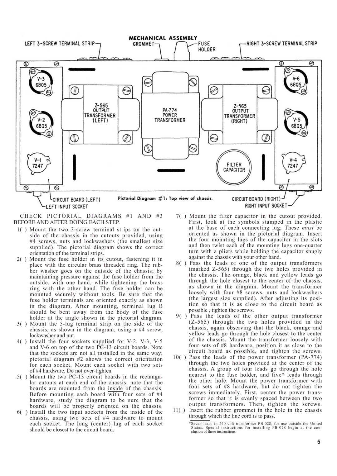
CHECK PICTORIAL DIAGRAMS #1 AND #3 BEFORE AND AFTER DOING EACH STEP.
1( ) Mount the two 3-screw terminal strips on the out- side of the chassis in the cutouts provided, using #4 screws, nuts and lockwashers (the smallest size supplied). The pictorial diagram shows the correct orientation of the terminal strips.
2( ) Mount the fuse holder in its cutout, fastening it in place with the circular brass threaded ring. The rub- ber washer goes on the outside of the chassis; by maintaining pressure against the fuse holder from the outside, with one hand, while tightening the brass ring with the other hand. The fuse holder can be mounted securely without tools. Be sure that the fuse holder terminals are oriented exactly as shown in the diagram. After mounting, terminal lug B should be bent away from the body of the fuse holder at the angle shown in the pictorial diagram.
3( ) Mount the 5-lug terminal strip on the side of the chassis, as shown in the diagram, using a #4 screw, lockwasher and nut.
4( ) Install the four sockets supplied for V-2, V-3, V-5 and V-6 on top of the two PC-13 circuit boards. Note that the sockets are not all installed in the same way; pictorial diagram #2 shows the correct orientation for each socket. Mount each socket with two sets of #4 hardware. Do not over-tighten.
5( ) Mount the two PC-13 circuit boards in the rectangu- lar cutouts at each end of the chassis; note that the boards are mounted from the inside of the chassis. Before mounting each board with four sets of #4 hardware, study the diagram to be sure that the boards will be properly oriented on the chassis.
6( ) Install the two input sockets from the inside of the chassis, using two sets of #4 hardware to mount each socket. The long (center) lug of each socket should be closest to the circuit board.
7( ) Mount the filter capacitor in the cutout provided. First, look at the symbols stamped in the plastic at the base of each connecting lug; These must be oriented as shown in the pictorial diagram. Insert the four mounting lugs of the capacitor in the slots and then twist each of the mounting lugs one-quarter turn with a pliers while holding the capacitor snugly against the chassis with your other hand.
8( ) Pass the leads of one of the output transformers (marked Z-565) through the two holes provided in the chassis. The orange, black and yellow leads go through the hole closest to the center of the chassis, as shown in the diagram. Mount the transformer loosely with four #8 screws, nuts and lockwashers (the largest size supplied). After adjusting its posi- tion so that it is as close to the circuit board as possible , tighten the screws.
9( ) Pass the leads of the other output transformer (Z-565) through the two holes provided in the chassis, again observing that the black, orange and yellow leads go through the hole closest to the center of the chassis. Mount the transformer loosely with four sets of #8 hardware, position it as close to the circuit board as possible, and tighten the screws.
10( ) Pass the leads of the power transformer (PA-774) through the two holes provided at the center of the chassis. A group of four leads go through the hole nearest to the fuse holder, and five* leads through the other hole. Mount the power transformer with four sets of #8 hardware, but do not tighten the screws immediately. First, center the power trans- former so that it is evenly spaced between the two output transformers. Then, tighten the screws.
11( ) Insert the rubber grommet in the hole in the chassis through which the line cord is to pass.
*Seven leads in 240-volt transformer PB-028, for use outside the United States. Special instructions for installing PB-028 begin at the con- clusion of these instructions.