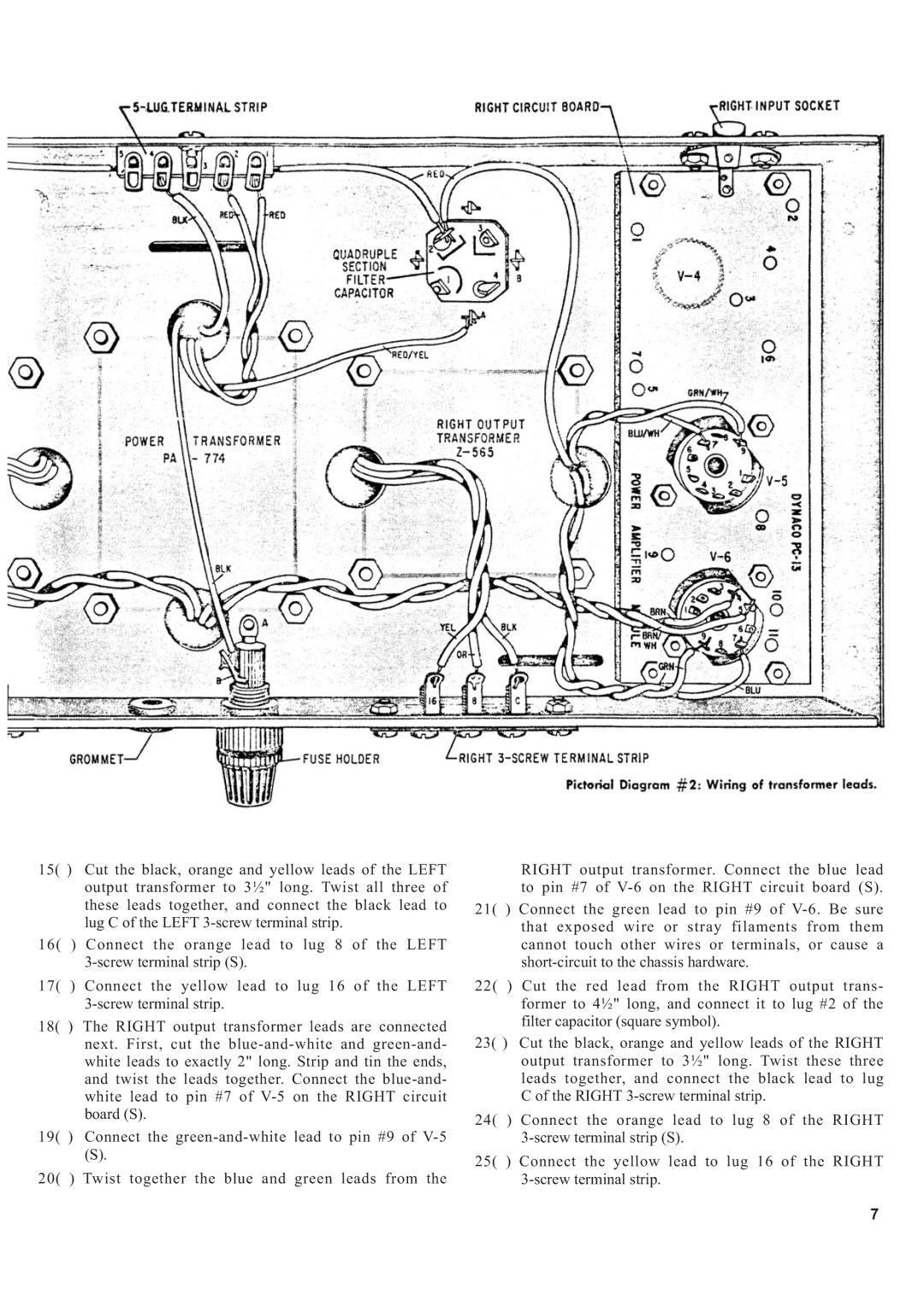
15( ) Cut the black, orange and yellow leads of the LEFT output transformer to 3½" long. Twist all three of these leads together, and connect the black lead to lug C of the LEFT
16( ) Connect the orange lead to lug 8 of the LEFT
17( ) Connect the yellow lead to lug 16 of the LEFT
18( ) The RIGHT output transformer leads are connected next. First, cut the
19( ) Connect the
(S).
20( ) Twist together the blue and green leads from the
RIGHT output transformer. Connect the blue lead to pin #7 of
21( ) Connect the green lead to pin #9 of
22( ) Cut the red lead from the RIGHT output trans- former to 4½" long, and connect it to lug #2 of the filter capacitor (square symbol).
23( ) Cut the black, orange and yellow leads of the RIGHT output transformer to 3½" long. Twist these three leads together, and connect the black lead to lug C of the RIGHT
24( ) Connect the orange lead to lug 8 of the RIGHT
25( ) Connect the yellow lead to lug 16 of the RIGHT
7