Wiring Diagram Hook Up Procedure
| Antenna |
|
| TV antenna | Power Harness |
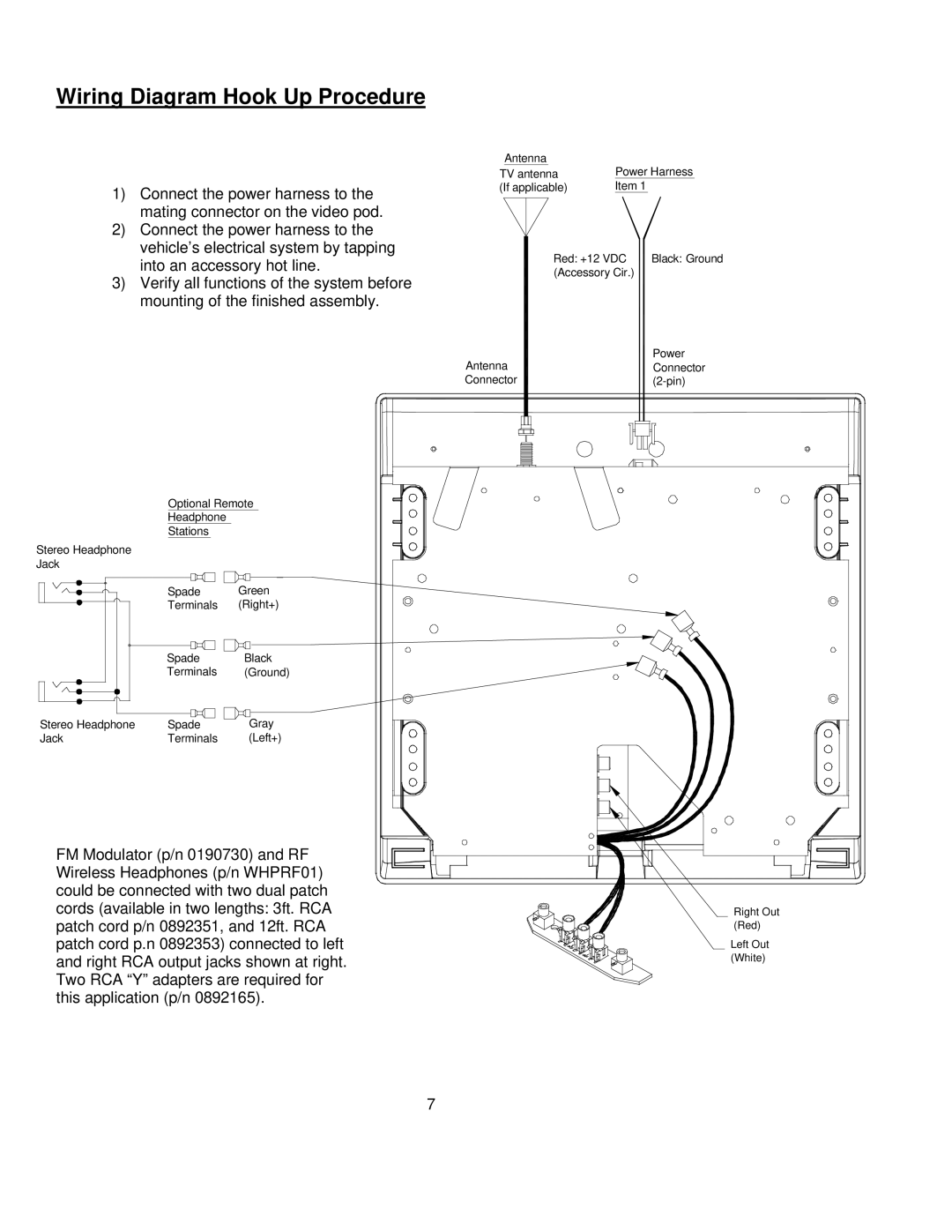
1) Connect the power harness to the | (If applicable) | Item 1 |
|
| |
mating connector on the video pod. |
|
|
2)Connect the power harness to the vehicle’s electrical system by tapping
into an accessory hot line. | Red: +12 VDC | Black: Ground |
(Accessory Cir.) |
| |
|
|
3)Verify all functions of the system before mounting of the finished assembly.
|
| Antenna | Power |
|
| Connector | |
|
| Connector | |
| Optional Remote |
| |
| Headphone |
|
|
| Stations |
|
|
Stereo Headphone |
|
|
|
Jack |
|
|
|
| Spade | Green |
|
| Terminals | (Right+) |
|
| Spade | Black |
|
| Terminals | (Ground) |
|
Stereo Headphone | Spade | Gray |
|
Jack | Terminals | (Left+) |
|
FM Modulator (p/n 0190730) and RF |
| ||
Wireless Headphones (p/n WHPRF01) |
| ||
could be connected with two dual patch |
| ||
cords (available in two lengths: 3ft. RCA | Right Out | ||
patch cord p/n 0892351, and 12ft. RCA | (Red) | ||
patch cord p.n 0892353) connected to left | Left Out | ||
and right RCA output jacks shown at right. | (White) | ||
| |||
Two RCA “Y” adapters are required for |
| ||
this application (p/n 0892165). |
| ||
|
| 7 |
|