2 |
Cable Diagram, No Optical Adapter
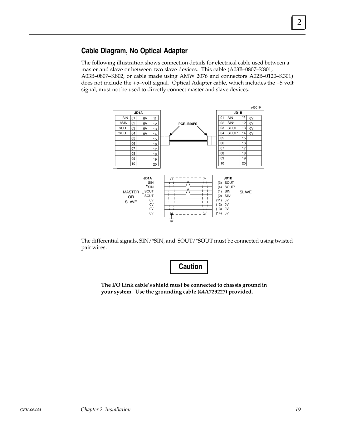
The following illustration shows connection details for electrical cable used between a master and slave or between two slave devices. This cable (A03B±0807±K801, A03B±0807±K802, or cable made using AMW 2076 and connectors A02B±0120±K301) does not include the +5±volt signal. Optical Adapter cable, which includes the +5 volt signal, must not be used to directly connect master and slave devices.
JD1A
| SIN | 01 | 0V | 11 |
|
|
| 8SIN | 02 | 0V | 12 |
|
|
| SOUT | 03 | 0V | 13 |
|
|
| *SOUT | 04 | 0V | 14 |
|
|
|
| 05 |
| 15 |
|
|
|
| 06 |
| 16 |
|
|
|
| 07 |
| 17 |
|
|
|
| 08 |
| 18 |
|
|
|
| 09 |
| 19 |
|
|
|
| 10 |
| 20 |
|
|
|
|
|
|
|
|
|
PCR±E20FS
|
|
|
|
|
| a45019 |
|
|
|
|
| JD1B |
|
| |
|
|
| 01 | SIN | 11 | 0V |
|
|
|
| 02 | SIN* | 12 | 0V |
|
|
|
| 03 | SOUT | 13 | 0V |
|
|
|
| 04 | SOUT* | 14 | 0V |
|
|
|
| 05 |
| 15 |
|
|
|
|
|
|
|
| ||
|
|
| 06 |
| 16 |
|
|
|
|
| 07 |
| 17 |
|
|
|
|
| 08 |
| 18 |
|
|
|
|
| 09 |
| 19 |
|
|
|
|
| 10 |
| 20 |
|
|
|
|
|
|
|
|
|
|
JD1A
SIN
*SIN
MASTER SOUT OR *SOUT
SLAVE 0V
0V
0V
0V
JD1B
(3)SOUT
(4)SOUT*
(1) SIN | SLAVE |
(2)SIN*
(11)0V
(12)0V
(13)0V
(14)0V
The differential signals, SIN/*SIN, and SOUT/*SOUT must be connected using twisted pair wires.
Caution
The I/O Link cable's shield must be connected to chassis ground in your system. Use the grounding cable (44A729227) provided.
Chapter 2 Installation | 19 |