2 |
Connecting the I/O Link Interface Module to Other Devices
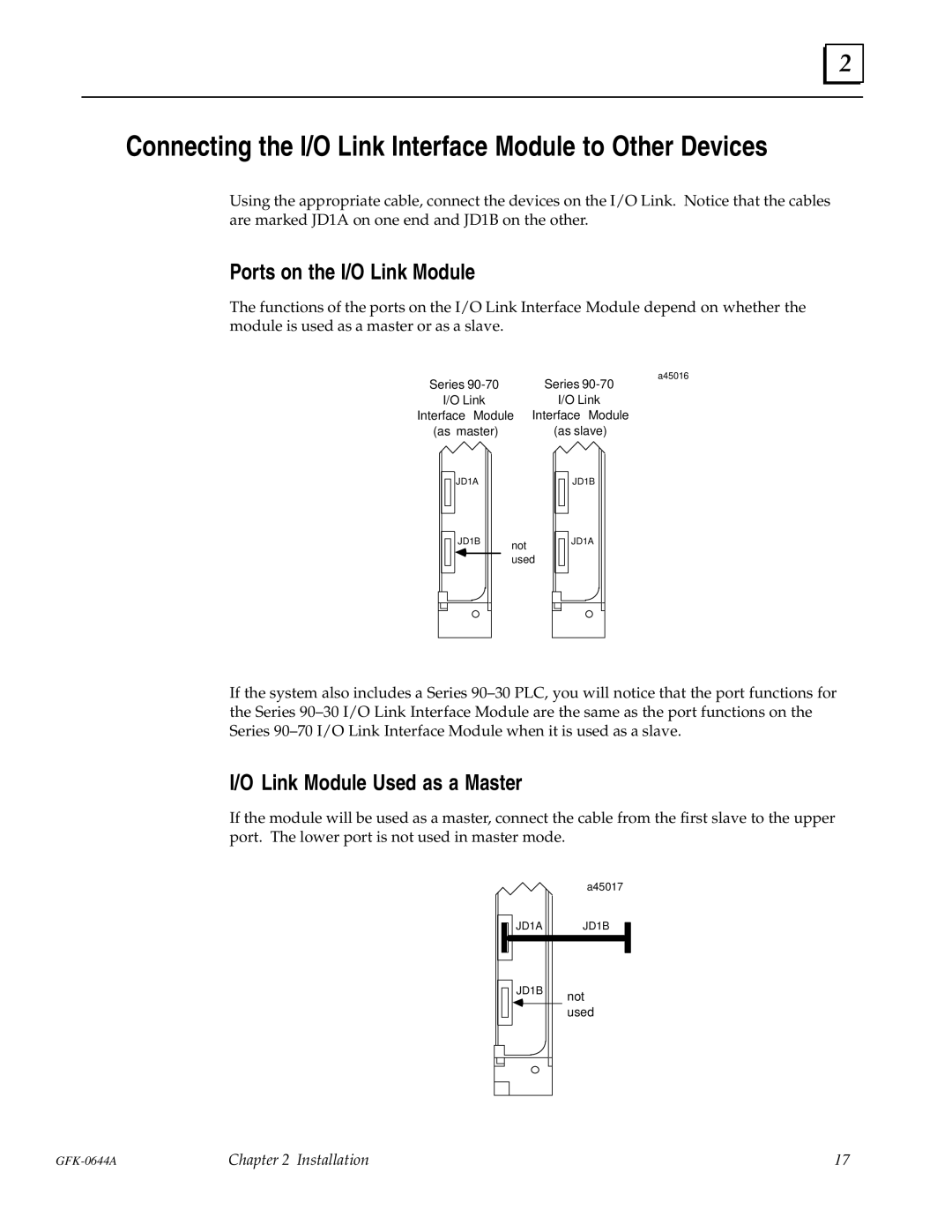
Using the appropriate cable, connect the devices on the I/O Link. Notice that the cables are marked JD1A on one end and JD1B on the other.
Ports on the I/O Link Module
The functions of the ports on the I/O Link Interface Module depend on whether the module is used as a master or as a slave.
a45016
Series | Series |
I/O Link | I/O Link |
Interface Module | Interface Module |
(as master) | (as slave) |
JD1A
JD1B
JD1B | not | |
|
| |
|
| used |
JD1A
If the system also includes a Series 90±30 PLC, you will notice that the port functions for the Series 90±30 I/O Link Interface Module are the same as the port functions on the Series 90±70 I/O Link Interface Module when it is used as a slave.
I/O Link Module Used as a Master
If the module will be used as a master, connect the cable from the first slave to the upper port. The lower port is not used in master mode.
|
|
|
| a45017 |
|
|
|
| JD1A | JD1B |
|
|
|
|
| ||
|
|
|
| ||
|
|
|
|
|
|
|
|
|
|
|
|
|
|
| JD1B | not |
|
|
|
|
| ||
|
|
|
| ||
|
|
|
|
|
used
Chapter 2 Installation | 17 |
