E. Controls, Indicators, and Connectors
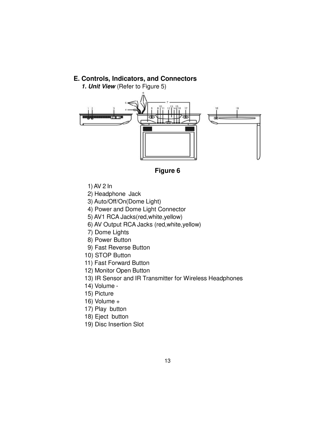
1.Unit View (Refer to Figure 5)
Figure 6
1)AV 2 In
2)Headphone Jack
3)Auto/Off/On(Dome Light)
4)Power and Dome Light Connector
5)AV1 RCA Jacks(red,white,yellow)
6)AV Output RCA Jacks (red,white,yellow)
7)Dome Lights
8)Power Button
9)Fast Reverse Button
10)STOP Button
11)Fast Forward Button
12)Monitor Open Button
13)IR Sensor and IR Transmitter for Wireless Headphones
14)Volume -
15)Picture
16)Volume +
17)Play button
18)Eject button
19)Disc Insertion Slot
13