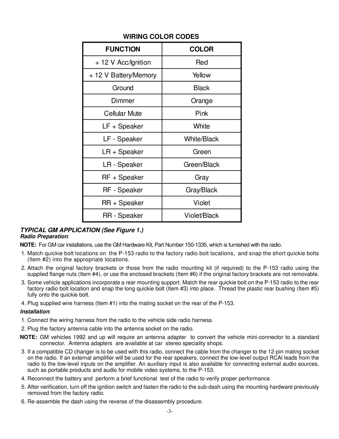
P-153 specifications
The Audiovox P-153 is a versatile and compact multimedia player that has gained popularity among tech enthusiasts for its advanced features and user-friendly design. This device bridges the gap between functionality and portability, making it an ideal companion for music lovers, gamers, and mobile professionals alike.One of the standout features of the Audiovox P-153 is its high-resolution display. The screen offers vibrant colors and sharp images, providing an immersive viewing experience whether you are watching videos or browsing photos. Its touchscreen interface enhances user interaction, allowing for intuitive navigation through menus and media libraries.
In terms of audio capabilities, the P-153 supports a wide range of formats, including MP3, WAV, and WMA, ensuring compatibility with various music sources. The built-in equalizer allows users to customize audio settings according to their preferences, enhancing the listening experience with tailored sound profiles. Additionally, the device is equipped with high-quality speakers that deliver clear and powerful audio, making it ideal for enjoying music or watching movies on the go.
The Audiovox P-153 also features advanced connectivity options, including Bluetooth and Wi-Fi capabilities. This allows users to stream music and videos directly from their smartphones or tablets, as well as connect to wireless headphones for an uninterrupted audio experience. The device is also compatible with various apps, enabling users to access streaming services and social media platforms seamlessly.
A notable characteristic of the P-153 is its robust battery life. With up to 10 hours of playback on a single charge, users can enjoy extended use without the need for constant recharging. The lightweight design and compact form factor make it easy to carry, fitting comfortably in bags or pockets, making it perfect for travel.
In summary, the Audiovox P-153 combines high-quality audio and video playback capabilities with modern connectivity options and a user-friendly interface. Its blend of portability and performance makes it a standout option for anyone looking for a reliable multimedia device. Whether for personal enjoyment or professional use, the P-153 caters to a diverse range of multimedia needs while ensuring that users stay connected and entertained on the go.
