POWER SUPPLY PANEL
FUNCTIONS
1
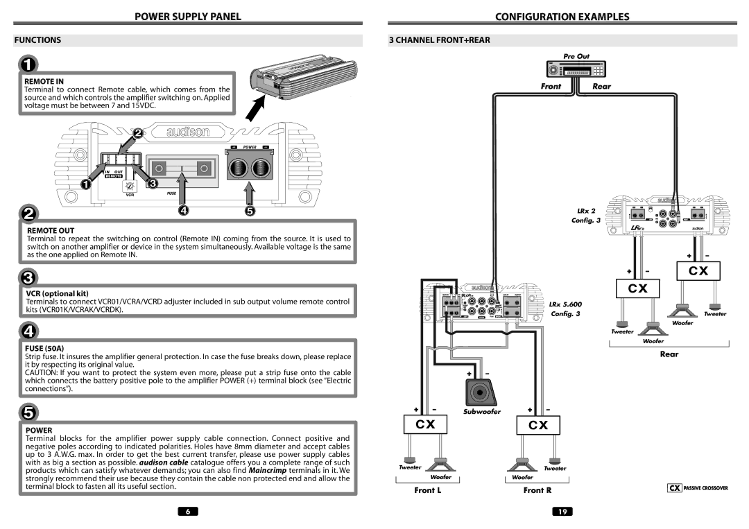
REMOTE IN
Terminal to connect Remote cable, which comes from the source and which controls the amplifier switching on. Applied voltage must be between 7 and 15VDC.
2![]()
CONFIGURATION EXAMPLES
3 CHANNEL FRONT+REAR
Pre Out
Front ![]()
![]() Rear
Rear
IN OUT
REMOTE
1
2
P O W E R
3
FUSE
45
LRx 2
Config. 3
REMOTE OUT
Terminal to repeat the switching on control (Remote IN) coming from the source. It is used to switch on another amplifier or device in the system simultaneously. Available voltage is the same as the one applied on Remote IN.
3
VCR (optional kit)
+
+
Terminals to connect VCR01/VCRA/VCRD adjuster included in sub output volume remote control kits (VCR01K/VCRAK/VCRDK).
4
FUSE (50A)
Strip fuse. It insures the amplifier general protection. In case the fuse breaks down, please replace it by respecting its original value.
CAUTION: If you want to protect the system even more, please put a strip fuse onto the cable which connects the battery positive pole to the amplifier POWER (+) terminal block (see “Electric connections”).
5
POWER
Terminal blocks for the amplifier power supply cable connection. Connect positive and negative poles according to indicated polarities. Holes have 8mm diameter and accept cables up to 3 A.W.G. max. In order to get the best current transfer, please use power supply cables with as big a section as possible. audison cable catalogue offers you a complete range of such products which can satisfy whatever demands; you can also find Maincrimp terminals in it. We strongly recommend their use because they contain the cable non protected end and allow the terminal block to fasten all its useful section.
+
Tweeter
Woofer
Front L
LRx 5.600 |
|
Config. 3 | Tweeter |
Woofer
Tweeter
Woofer
Rear
+
Subwoofer +
Tweeter
Woofer
Front R
6 | 19 |
