| CONTROLS PANEL |
| CONFIGURATIONS | |
|
|
|
|
|
|
|
|
|
|
|
|
| ||
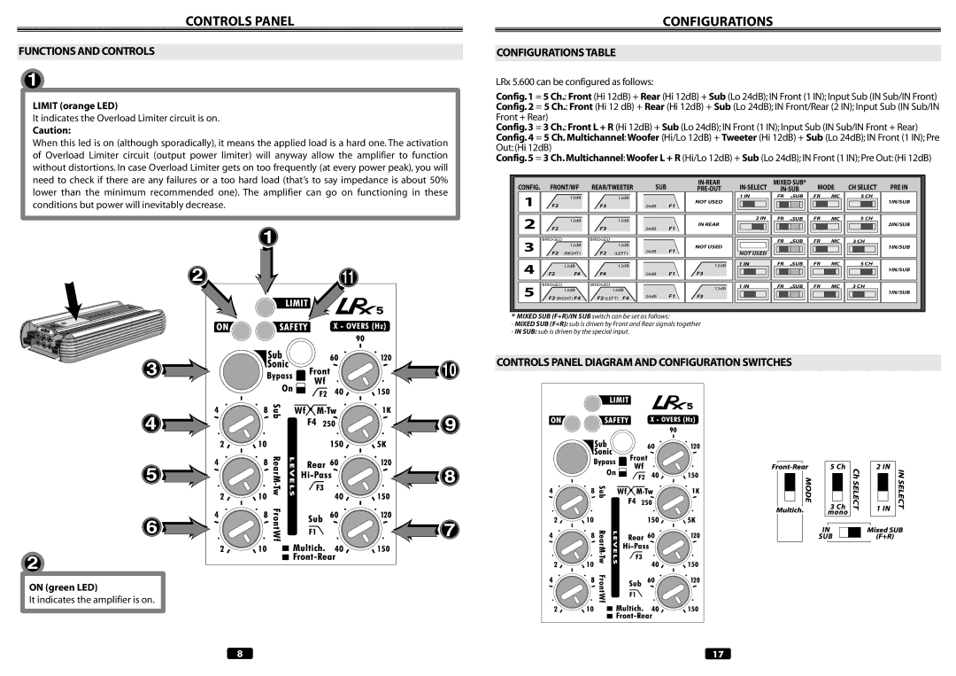
FUNCTIONS AND CONTROLS |
|
| ||
| CONFIGURATIONS TABLE | |||
| 1 |
|
| LRx 5.600 can be configured as follows: |
| LIMIT (orange LED) |
| Config. 1 = 5 Ch.: Front (Hi 12dB) + Rear (Hi 12dB) + Sub (Lo 24dB); IN Front (1 IN); Input Sub (IN Sub/IN Front) | |
|
| Config. 2 = 5 Ch.: Front (Hi 12 dB) + Rear (Hi 12dB) + Sub (Lo 24dB); IN Front/Rear (2 IN); Input Sub (IN Sub/IN | ||
| It indicates the Overload Limiter circuit is on. |
| Front + Rear) | |
Caution: |
| Config. 3 = 3 Ch.: Front L + R (Hi 12dB) + Sub (Lo 24dB); IN Front (1 IN); Input Sub (IN Sub/IN Front + Rear) | |||||||||||||||
| Config. 4 = 5 Ch. Multichannel: Woofer (Hi/Lo 12dB) + Tweeter (Hi 12dB) + Sub (Lo 24dB); IN Front (1 IN); Pre | ||||||||||||||||
When this led is on (although sporadically), it means the applied load is a hard one. The activation | |||||||||||||||||
Out: (Hi 12dB) |
|
|
|
|
|
|
|
|
|
|
|
|
| ||||
of Overload Limiter circuit (output power limiter) will anyway allow the amplifier to function |
|
|
|
|
|
|
|
|
|
|
|
|
| ||||
Config. 5 = 3 Ch. Multichannel: Woofer L + R (Hi/Lo 12dB) + Sub (Lo 24dB); IN Front (1 IN); Pre Out: (Hi 12dB) | |||||||||||||||||
without distortions. In case Overload Limiter gets on too frequently (at every power peak), you will |
|
|
|
|
|
|
|
|
|
|
|
|
|
|
| ||
need to check if there are any failures or a too hard load (that’s to say impedance is about 50% | CONFIG. | FRONT/WF | REAR/TWEETER | SUB |
| MIXED SUB* | MODE | CH SELECT | PRE IN | ||||||||
lower than the minimum recommended one). The amplifier can go on functioning in these |
| ||||||||||||||||
1 |
| 12dB |
| 12dB |
|
| NOT USED | 1 IN | FR | *SUB | FR | MC | 5 CH | 1IN/SUB | |||
conditions but power will inevitably decrease. |
| F2 |
| F3 |
| 24dB | F1 |
|
|
|
|
|
| ||||
|
|
|
|
|
|
|
|
|
|
| |||||||
|
| 2 |
| 12dB |
| 12dB |
|
| IN REAR | 2 IN | FR | *SUB | FR | MC | 5 CH | 2IN/SUB | |
| 1 | F2 |
| F3 |
| 24dB | F1 |
|
|
|
|
|
| ||||
|
|
|
|
|
|
|
|
|
|
| |||||||
| 3 | BRIDGED |
| BRIDGED |
|
|
|
|
| FR | *SUB | FR | MC | 3 CH |
| ||
|
| 12dB |
| 12dB |
|
| NOT USED |
| 1IN/SUB | ||||||||
|
|
|
|
|
| 24dB | F1 |
|
|
|
|
|
| ||||
|
| F2 | (RIGHT) | F2 | (LEFT) |
| NOT USED |
|
|
|
|
|
| ||||
|
|
|
|
|
|
|
|
|
|
|
| ||||||
2 | 11 | 4 |
| 12dB |
| 12dB |
|
| 12dB | 1 IN | FR | *SUB | FR | MC | 5 CH | 1IN/SUB | |
F2 | F4 | F4 |
| 24dB | F1 | F3 |
|
|
|
|
|
| |||||
|
|
|
|
|
|
|
| ||||||||||
5 | BRIDGED |
| BRIDGED |
|
|
| 12dB | 1 IN | FR | *SUB | FR | MC | 3 CH |
| |||
|
|
| 12dB |
| 12dB |
|
| 1IN/SUB | |||||||||
|
|
|
|
|
|
|
|
|
|
|
|
| |||||
|
|
|
|
|
| 24dB | F1 | F3 |
|
|
|
|
|
| |||
|
| F2 (RIGHT) F4 | F2 (LEFT) F4 |
|
|
|
|
|
|
| |||||||
|
| * MIXED SUB (F+R)/IN SUB switch can be set as follows: |
|
|
|
|
|
|
|
| |||||||
|
| - MIXED SUB (F+R): sub is driven by Front and Rear signals together |
|
|
|
|
|
|
| ||||||||
|
| - IN SUB: sub is driven by the special input. |
|
|
|
|
|
|
|
|
|
| |||||
3 ![]()
4 ![]()
5 ![]()
6 ![]()
2
ON (green LED)
It indicates the amplifier is on.
10
![]() 9
9
![]() 8
8
![]() 7
7
CONTROLS PANEL DIAGRAM AND CONFIGURATION SWITCHES
8 | 17 |