Assembly Instructions

NOTE: Refer to Assembly Diagram on pages 21 and 22. It may be easier to position grill on its back side for assembly. Do not tighten bolts and nuts completely until told to do so.

Bolts are shown actual size.

Tools Required:

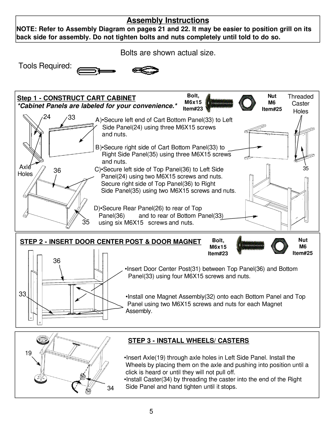
Step 1 - CONSTRUCT CART CABINET


Bolt,


Nut

Threaded


*Cabinet Panels are labeled for your convenience.*


M6x15


M6

Caster


Item#23


Item#25

Holes


24

33

A)•Secure left end of Cart Bottom Panel(33) to Left


Side Panel(24) using three M6X15 screws


and nuts.

B)•Secure right side of Cart Bottom Panel(33) to Right Side Panel(35) using three M6X15 screws and nuts.


Axle


35


36


C)•Secure left side of Top Panel(36) to Left Side


Holes


Panel(24) using two M6X15 screws and nuts.


Secure right side of Top Panel(36) to Right


Side Panel(35) using two M6X15 screws and nuts.


D)•Secure Rear Panel(26) to rear of Top


35


Panel(36)

and to rear of Bottom Panel(33)


using six M6X15 screws and nuts.


STEP 2 - INSERT DOOR CENTER POST & DOOR MAGNET


Bolt,


Nut


M6x15


M6


36


Item#23


Item#25


•Insert Door Center Post(31) between Top Panel(36) and Bottom Panel(33) using four M6X15 screws and nuts.

33

•Install one Magnet Assembly(32) onto each Bottom Panel and Top


Panel using two M6X15 screws and nuts for each Magnet


Assembly.

STEP 3 - INSTALL WHEELS/ CASTERS

19


•Insert Axle(19) through axle holes in Left Side Panel. Install the


Wheels by placing them on the axle and pushing into position until a


click is heard or until they will not pull off.


•Install Caster(34) by threading the caster into the end of the Right


Side Panel and hand tighten until it stops.


34


5

Page 5
Image 5
Aussie 8462, 8362 manual Construct Cart Cabinet, Insert Door Center Post & Door Magnet, Install WHEELS/ Casters

8362, 8462 specifications

Aussie 8462,8362 are two advanced models that showcase the innovation in modern technology, particularly in the field of telecommunications and data transmission. These models are a testament to Australia’s growing influence in the tech sector, particularly in developing solutions that cater to both local and international markets.

One of the main features of the Aussie 8462 is its exceptional data processing capacity. This model is engineered to handle large volumes of data with remarkable efficiency, making it ideal for businesses that rely on real-time analytics. Additionally, the 8462 incorporates advanced encryption technologies, ensuring that data remains secure during transmission. This feature is increasingly important in an era where data breaches are rampant, and businesses must prioritize customer privacy.

On the other hand, the Aussie 8362 focuses more on connectivity and versatility. It has been designed to support multiple connectivity options, including 5G, LTE, and Wi-Fi 6. This variety allows it to cater to a wide range of devices, ensuring seamless communication in diverse environments. Moreover, the 8362 is equipped with smart routing capabilities that optimize network traffic, thereby enhancing overall performance and reducing latency.

Both models employ state-of-the-art artificial intelligence algorithms to facilitate predictive analysis and automate network management tasks. This functionality significantly reduces the need for manual intervention, allowing IT departments to focus on strategic initiatives rather than routine maintenance.

In terms of physical characteristics, both the 8462 and 8362 boast rugged and compact designs, suitable for various installation environments. They are built with durable materials that can withstand extreme weather conditions, making them ideal for outdoor deployments. Furthermore, their energy-efficient architecture ensures that they consume less power while delivering high performance, contributing to sustainability efforts.

In conclusion, the Aussie 8462 and 8362 represent a significant advancement in telecommunications technology. Their integration of robust security features, advanced connectivity options, and intelligent network management systems makes them suitable for modern businesses looking to thrive in a digital-first world. As Australia continues to innovate in this space, these models set a benchmark for future developments in telecommunications technology.